![]()
Single chip microcomputer STM32L151CCU6
![]()
1206 red anti-stick
![]()
Photocoupler
The 555 circuit contains two voltage comparators, a basic RS flip-flop and a discharge switch T. The comparator's reference voltage is provided by a voltage divider consisting of three 5K resistors. They respectively make the non-inverting input of the high-level comparator A1 and the inverting of the low-level comparator A2, and the reference levels of the input terminals are 2/3VCC and 1/3VCC. The outputs of the A2 and A2 control the RS flip-flop state and Discharge tube switch status. When the input signal is from the 6 pin, that is, the high level triggers the input and exceeds the reference level 2/3VCC, the flip-flop resets, the output of the 555 pin 3 outputs a low level, and the discharge switch tube is turned on; when the input signal is from 2 The input of the pin is lower than 1/3VCC, the trigger is reset, the 3 pin of 555 outputs high level, and the discharge switch tube is cut off. RD is the reset terminal (4 pins). When RD=0, 555 outputs a low level. Usually the RD end is open or connected to VCC.
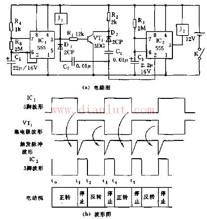
Motor forward and reverse controller circuit diagram 