Both spectrum analyzers and oscilloscopes are commonly used electronic measuring instruments and are widely used in many industries. There is also a big difference between the spectrum analyzer and the oscilloscope. Have we seen the difference between the spectrum analyzer and the oscilloscope? This is also very important for the user's choice. Today, Xiaobian will introduce the difference between the spectrum analyzer and the oscilloscope.
First, we compare the differences in analytical performance metrics between oscilloscopes and spectrum analyzers in terms of real-time bandwidth, dynamic range, sensitivity, and power measurement accuracy.
1, real-time bandwidthFor an oscilloscope, the bandwidth is usually the range of its measurement frequency. The spectrum analyzer has bandwidth definitions such as IF bandwidth and resolution bandwidth. Here, we discuss the real-time bandwidth that enables real-time analysis of signals.
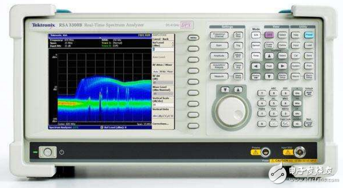
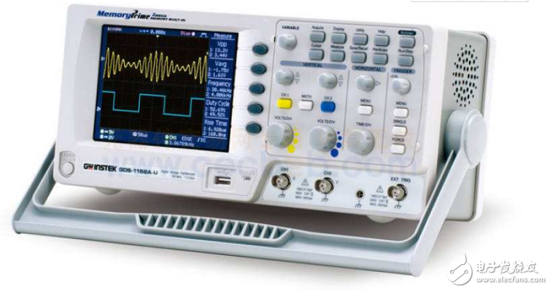
For the spectrum analyzer, the bandwidth of the final analog IF can usually be used as the real-time bandwidth of its signal analysis. The real-time bandwidth of most spectrum analysis is only a few megahertz. Usually the wide real-time bandwidth is usually several tens of megahertz. The widest bandwidth FSW spectrum analyzer can reach 500 MHz. The real-time bandwidth of the oscilloscope is the effective analog bandwidth for real-time sampling, typically hundreds of megahertz and high up to several gigahertz.

Graph spectrum analyzer
It should be noted here that most oscilloscopes may have inconsistent real-time bandwidth when the vertical scale settings are different. When the vertical scale is set to the most sensitive, the real-time bandwidth is usually reduced.
In terms of real-time bandwidth, oscilloscopes are generally superior to spectrum analyzers, which is especially beneficial for some ultra-wideband signal analysis, especially in modulation analysis.
2, dynamic rangeDynamic range metrics vary by definition. In many cases, dynamic range is described as the instrument's measurement of the difference between the maximum signal and the minimum signal. When changing the measurement settings, the instrument's ability to measure large and small signals is different. For example, if the spectrum analyzer has different attenuation settings, the distortion caused by measuring large signals is different. Here, we discuss the ability of the instrument to simultaneously measure large and small signals, ie the optimal dynamic range of the oscilloscope and spectrum analyzer with the appropriate settings without changing any measurement settings.
For the spectrum analyzer, the average noise level, second-order distortion, and third-order distortion are the most important factors that restrict the dynamic range, regardless of the near-end noise and spurs such as phase noise, and are calculated by the technical specifications of the mainstream spectrum analyzer. Its ideal dynamic range is approximately 90dB (limited by second-order distortion).
Most oscilloscopes typically have an ideal dynamic range of less than 50 dB due to their AD effective sample count and noise floor. (For R&SRTO oscilloscopes, the dynamic range is up to 86dB at 100KHz RBW)

Oscilloscope
From a dynamic range, the spectrum analyzer is better than an oscilloscope. However, it should be pointed out here that this is true for the spectrum analysis of the signal. However, the spectrum of the oscilloscope is the same frame data, and the spectrum of the spectrum analyzer is not the same frame data in most cases, so for transient signals. The spectrum analyzer may not be able to measure it. The oscilloscope is much more likely to find transient signals (where the signal meets the dynamic range).
3. SensitivityThe sensitivity discussed here refers to the level at which the oscilloscope and the spectrum analyzer can detect the minimum signal. This indicator is closely related to instrument settings.
For the oscilloscope, when the oscilloscope is set to the most sensitive file in the Y-axis, the oscilloscope can test the minimum signal when the oscilloscope is usually 1mV/div, and the noise of the oscilloscope's signal channel and the trajectory are not observed. The noise caused by stability is the most important factor that limits the sensitivity of the oscilloscope.
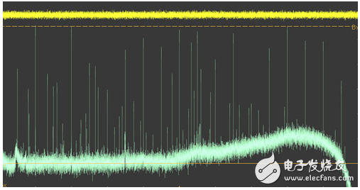
As can be seen from Figure 1, because of the increase in the number of sampling points, the spectral noise floor can be reduced to a desired level. However, when the signal cannot be reproduced clearly and accurately in the time domain, a lot of clutter is generated in the frequency domain, which limits our ability to observe small signals.

Figure 1 Sensitivity limits affected by noise
Most oscilloscopes, as shown in Figure 1, are capable of stably measuring a 0.2mV signal, corresponding to the frequency domain, which is equivalent to a level of -60dBm. In fact, whether the oscilloscope can accurately measure small signals is not only related to the sensitivity of the vertical system, but also related to the X-axis jitter and trigger sensitivity.
2.54mm (0.1") Pitch Female Headers
Overview
The most commonly seen female headers are 2.54mm (0.1") single or double row female/socket headers. These female headers together with its male counterpart are used in connecting Arduino boards and shields together. 2.54mm pitch female sockets/headers are low-profile connectors designed for signal and low power PC board connections when space is at a premium. They have the perfect height for clearing the USB-B connector and great for stacking multiple shields.
Since 2.54mm pitch female header is commonly used in a lot of applications, Scondar offers numerous options for this type of female header. Orientation can either be SMT or THM, single, dual or triple row. Antenk offers 2.54mm pitch female headers in either vertical or right-angle orientation. The pins and blades are also available in various sizes, counts, amperages, and plating.
The 2.54mm can accommodate a maximum current of 3A, with a 30 to 22 AWG wire size, and up to 40-positions. Antenk offers these female headers in high quality and affordable China-quoted price that snuggly fits with the pins of a male header and acts as a receptacle.
If you can not find the items you interest from above items, welcome to contact us, and you will always get fully responsive from us.
Applications of 2.54mm Pitch Female Headers
Electronics:
LED applications
Arduino boards
Arduino Pro
Arduino Mega
Solar applications
Weighing systems
Appliances:
Air conditioner
Refrigerator
Microwave oven
Washing machine
Water heater
Shower toilet
Washer/Dryer
Stove
Automotive, Heavy Duty Military and Marine
For densely packed equipment requiring weight reduction and downsizing and for tough and harsh conditions.
Vehicle infotainment
Computer peripherals
Battery Connections
Battery connections rely on the ability of the current to pass reliable and solid current. This prevents overheating in the circuit and voltage drop.
Rechargeable battery packs
Battery balancers
Battery eliminator circuits
Medical Diagnostic and Monitoring equipment
Heart monitors
Telecoms
Datacoms
Mount Type: Through-hole vs Surface Mount
At one side of this female header is a series of pins which can either be mounted and soldered directly onto the surface of the PCB (SMT) or placed into drilled holes on the PCB (THM).
Through-Hole (Poke-In)
Best used for high-reliability products that require stronger connections between layers.Aerospace and military products are most likely to require this type of mounting as these products experience extreme accelerations, collisions, or high temperatures.
Useful in test and prototyping applications that sometimes require manual adjustments and replacements.
2.54mm, 1-row vertical female header, 2.54mm, 2-row vertical female header, 2.54mm, 3-row vertical female header, 2.54mm, 1-row right-angle female header and 2.54mm, 2-row right-angle female header, 2.54mm U-
Shaped Female header, 2.54mm U-Shaped Dual Row Female header are examples of Antenk products with through-hole mount type.
Surface-Mount
The most common electronic hardware requirements are SMT.
Essential in PCB design and manufacturing, having improved the quality and performance of PCBs overall.
Cost of processing and handling is reduced.
SMT components can be mounted on both side of the board.
Ability to fit a high number of small components on a PCB has allowed for much denser, higher performing, and smaller PCBs.
2.54mm, 2-row right-angle female header and 2.54mm, 1-row right-angle female header are Antenk`s featured SMT female headers.
Orientation/Pin-Type: Vertical (Straight), Right-Angle and U-Shaped
2.54mm pitch female headers may be further classified into pin orientation as well, such as vertical or straight female header, right-angle female header or U-shaped female header.
Vertical or Straight Female Header Orientation
One side of the series of pins is connected to PCB board in which the pins can be at a right-angle to the PCB surface (usually called "straight" or [vertical") or..
Right-Angle Female Header Orientation
Parallel to the board's surface (referred to as "right-angle" pins).
U-Shaped Female Header Orientation
U-shaped orientation is characterized by the shape of the pins at one side of the header, forming a letter [U". It is often chosen for applications where repeat mating cycles are not required as it can also be used and soldered directly to both PCB's.
Each of these pin-types have different applications that fit with their specific configuration.
Single, Dual or Multiple Number of Rows
For a 2.54mm straight or vertical female header, the standard number of rows that Antenk offers ranges from 1 to 2 rows. However, customization can be available if 3, 4 or n number of rows is needed by the customer. Also, the number of contacts for the single row is about 2-40 pins while for dual row, the number contacts may vary from 2-80 pins.
Pin Material
The pins of the connector attached to the board have been designed with copper alloy. With customer`s demand the pins can be made gold plated.
Custom 2.54mm Pitch Female Headers
Customizable 2.54 mm pitch female headers are also available, making your manufacturing process way faster as the pins are already inserted in the headers, insulator height is made at the right size and the accurate pin length you require is followed.
Parts are made using semi-automated manufacturing processes that ensure both precision and delicacy in handling the headers before packaging on tape and reel.
Tape and Reel Packaging for SMT Components
Antenk's SMT headers are offered with customizable mating pin lengths, in which each series has multiple number of of circuits, summing up to a thousand individual part number combinations per connector series.
The tape and reel carrier strip ensures that the headers are packaged within accurately sized cavities for its height, width and depth, securing the headers from the environment and maintaining consistent position during transportation.
Antenk also offer a range of custom Tape and reel carrier strip packaging cavities.
Pcb Header Connector,2.54Mm Female Pin Header,2.54Mm Pcb Header,2.54Mm Pcb Connector,0.1" Pitch Female Headers,2.54mm SMT Female Pin Header, THT 2.54mm Female Pin Header
ShenZhen Antenk Electronics Co,Ltd , https://www.antenk.com
