
Flyback power supplies are a sensible choice when choosing a system topology that produces multiple outputs from a single supply. Since the voltage on each transformer winding is proportional to the number of turns in the winding, each output voltage can be easily set by the number of turns. Ideally, if you adjust one of the output voltages, all other outputs will be scaled by the number of turns and will remain stable.
However, in reality, parasitic elements will collectively reduce the load adjustment of the unregulated output. In this power supply tip, I will further explore the effects of parasitic inductance and how to use synchronous rectification instead of diodes to significantly improve the cross regulation of flyback power supplies.
For example, a flyback power supply can generate two 1 A 12V outputs from a single 48V input, as shown in the simplified simulation model of Figure 1. The ideal diode model has a zero forward voltage drop and the resistance is negligible. The transformer winding resistance is negligible and only the parasitic inductance in series with the transformer leads can be modeled. These inductors are the leakage inductance in the transformer, as well as the parasitic inductance in printed circuit board (PCB) traces and diodes. When these inductors are set, the two outputs track each other because when the diode is turned on during the 1-D portion of the switching cycle, the full coupling of the transformer causes the two outputs to be equal.
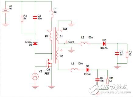
Figure 1. This flyback simplified model simulates the effect of leakage inductance on output voltage regulation.
Now consider what happens when you introduce 100 nH of leakage inductance into the two secondary leads of the transformer and triple the leakage of 3μH to the primary winding. These inductors create parasitic inductance in the current path, including leakage inductance inside the transformer and inductance in the PCB and other components. When the initial field effect transistor (FET) is turned off, the initial leakage inductance still has current flowing, while the secondary leakage inductance turns on the initial condition of 0 A for 1-D periods. The pedestal voltage appears on the transformer core and all windings are shared. The pedestal voltage ramps the current in the primary leakage to 0 A and ramps the secondary leakage current to deliver current to the load.
When the two heavy loads are output, the current continues to flow throughout the 1-D period, and the output voltage is well balanced, as shown in Figure 2. However, when one heavy-duty output and the other light-loaded output, the output capacitance on the light-load output tends to peak from the susceptor voltage; because the current quickly rises back to zero, its output diode will stop conducting. See the waveform in Figure 3. The peak charge cross regulation effects of these parasitic inductances are typically much worse than the rectifier forward voltage drop alone.
Figure 2 When a heavy load is applied to two outputs, the secondary winding current flows in the two secondary windings throughout the 1-D period. You can see the pedestal voltage on the red trace above.
Figure 3 Heavy load secondary 1 and light load secondary 2. The pedestal voltage peaks the output capacitor of the secondary 2.
Regardless of the load, the synchronous rectifier helps to alleviate this problem by forcing current into the two windings over the entire 1-D period. Figure 4 shows the waveform with the same load conditions as Figure 3, but with an ideal synchronous rectifier instead of the ideal diode. Since the synchronous rectifier remains in good condition after the pedestal voltage is reduced, the two output voltages track each other well even in the presence of a severely unbalanced load.
Although the average current of the secondary 2 is very small, the root mean square (RMS) content can still be quite high. This is because, unlike the ideal diode in Figure 3, the synchronous rectifier can force a continuous current flow during the entire 1-D period. Interestingly, the current must be negative for most of this cycle to ensure a low average current.
Obviously, you sacrifice better adjustments to achieve higher circulating currents. However, this does not necessarily mean that the total loss will be higher. Synchronous rectifiers typically have a much lower forward voltage drop than diodes, so synchronous rectifiers are typically much more efficient at higher loads.
Figure 4 replaces the diode with a synchronous rectifier to force current to flow in both secondary windings and eliminates peak charging of the susceptor voltage.
You can see the effect on cross regulation in Figure 5. The load on output 1 remains stable at 1A, while the load on output 2 fluctuates between 10 mA and 1A. At loads below 100 mA, when diodes are used, cross regulation is severely degraded due to the effects of peak charging of the susceptor voltage.
Keep in mind that you only see the effects of leakage inductance because the ideal diodes and ideal synchronous rectifiers are used in these simulations. The advantages of using a synchronous rectifier are further highlighted when considering the effects of the forward voltage drop of the resistor and the rectifier.
Therefore, in order to achieve excellent cross regulation in a multi-output flyback power supply, consider using a synchronous rectifier. In addition, you may also increase the efficiency of your power supply. View TI's 40V to 60V Input 40W Dual Output Isolated Flyback Converter (6V at 4.33A) and Class 3 Dual Output Isolated Flyback Converter for Use in PoE Application Reference Designs as Flyback Power Supplies Using Synchronous Rectifiers Example.
Figure 5 This figure shows the cross regulation between the two outputs, where the 1-A load on output 1 remains stable and the load on output 2 changes continuously, highlighting how the synchronous rectifier mitigates the effects of leakage inductance.
Intelligent charging logo and fast charging: This 100 port USB charger automatically identifies the current signal and performs the current output according to the device restriction. The device is limited to intelligent and secure. Just plug in, no driver or software is required. The latest generation of USB hub controller, the maximum charging output of each USB port 3.5A. Single -port supports fast charging to save your time and energy. 100 % security charging: This 100 port USB charging station built -in smart chip is to prevent voltage from exceeding the current and overload. Reasonable cooling holes can effectively dissipate heat to prevent excessive excessiveness. Excessive charging protection, when these devices are fully charged, they will automatically convert to small charges flowing current, and the battery saturation rate is 99 %.

100 Port Usb Charger,100 Port Usb Wall Charger,Multi Port Usb Hub Charger,100 Port Usb Charging Station
shenzhen ns-idae technology co.,ltd , https://www.szbestchargers.com