
With the emergence of many new technologies, people increasingly need to use 3D methods to represent objects in the real world. Especially machine vision and robotics, they all benefit from precise and adaptive 3D capture. Other applications for 3D scanning include biometrics, security, industrial inspection, quality control, medical, dental and prototyping.
A 3D scan is the extraction of the surface and physical measurements of an object and its representation in digital form. These data are collected as a point cloud consisting of X, Y and Z coordinates (representing the external surface of the object). Analysis of a 3D scan can determine the surface area, volume, surface shape, shape, and feature size of the object being scanned.
A 3D scanner requires a probe to determine the distance to each point on the surface of the object. In theory, this probe can be a tactile (physical contact) probe. However, many applications require non-contact measurements. Optical techniques that use only illumination to detect objects of interest present a solution to this problem. One of the methods uses at least two cameras to provide stereoscopic vision technology, which is often more computationally demanding and sensitive to ambient lighting conditions. Another method uses structured illumination graphics, which requires only one projector (for generating light patterns) and a single camera and medium-sized algorithm.
Structured Light structured light is an optical method of 3D scanning that projects a set of mathematically constructed light patterns that illuminate the object being measured in a certain order. A camera with a known distance to the projector simultaneously captures an image of a group of illuminated objects. The pattern seen by the camera is distorted by the surface shape of the scanned object relative to the planar reference surface used for calibration. The principle of geometric triangulation makes it possible to calculate the XYZ coordinates of each point on the surface of the object being scanned (see Figure 01). The obtained point cloud data is then used for the computational construction of the detailed 3D model of the surface of the scanned object.
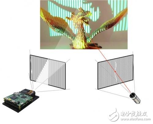
Figure 01: Structured light using DLP® technology
Programmable Graphic Structure Light The programmable graphics scanner projects a series of graphics onto the surface of the object using a laser or LED light source with a digital spatial light modulator (SLM). By using multiple graphics, a programmable structured light scanner can achieve higher accuracy and can change graphics based on ambient lighting conditions, object surface, and object light reflection characteristics.
Since the programmable graphics structure requires multiple graphics to be displayed, the spatial light modulator becomes a key component of such scanners. There are a number of spatial light modulation technologies available on the market, including Texas Instruments DLP® technology, specifically the DLP6500 and DLP9000 chipsets.
Different structured light scanning algorithms require the SLM to be able to produce one of the secondary or grayscale graphics, or to be able to produce both graphics. High-contrast graphics help maximize accuracy and reliable operation while handling changing object reflectance and ambient light conditions. Due to size, cooling and battery requirements, the system design takes light flux and energy efficiency as a top priority.
There are many techniques for optimizing 3D structured light patterns. One particularly effective method is the adaptive graphics set. The algorithm determines the best combination of graphics and wavelength to improve the resolution of the object being scanned. Depending on the color of the object, you can choose a variable color (wavelength of light). Adaptive graphics improve the ability to scan objects with complex or discontinuous surface textures.
Design Considerations There are several important design considerations when designing a programmable structured light solution. The size and distance of the object being measured and the spatial accuracy required for 3D measurements determine the performance characteristics of the required spatial light modulator and graphics capture camera. The SLM resolution (number of pixels) and the field size (pixels/mm) determine the achievable accuracy. The resolution of the camera must be large enough, and according to the sampling theorem, it should normally be at least four times the density of the SLM pixel.
During the scan, any movement of the object can obscure the data, which reduces the measurement accuracy. In order to achieve the desired level of 3D accuracy, the faster the object moves, the faster it must perform a full scan. The faster the scan requires a faster spatial light modulator and a higher frame capture rate camera, and the higher brightness of the graphic illumination will also help with fast scanning. In different 3D measurement systems, it may be necessary to go from several times per second to a maximum of hundreds of graphics rates per second.
Conclusion Machine and robot vision and other 3D applications are making smart machines more and more powerful. 3D scanning continues to evolve with the development of new technologies and algorithms. As processing and sensor capabilities continue to increase, and their cost is steadily declining, these new technologies give end users more choice. Active, non-contact 3D scanning systems with structured light offer users unique advantages, but these systems must be evaluated for specific application needs.
references
Geng, Jason: Structural Light 3D Surface Imaging: Tutorial
Koninckx, Thomas P. and Gool, Luc Van: Real-time range acquisition with adaptive structured light
gree , https://www.greegroups.com