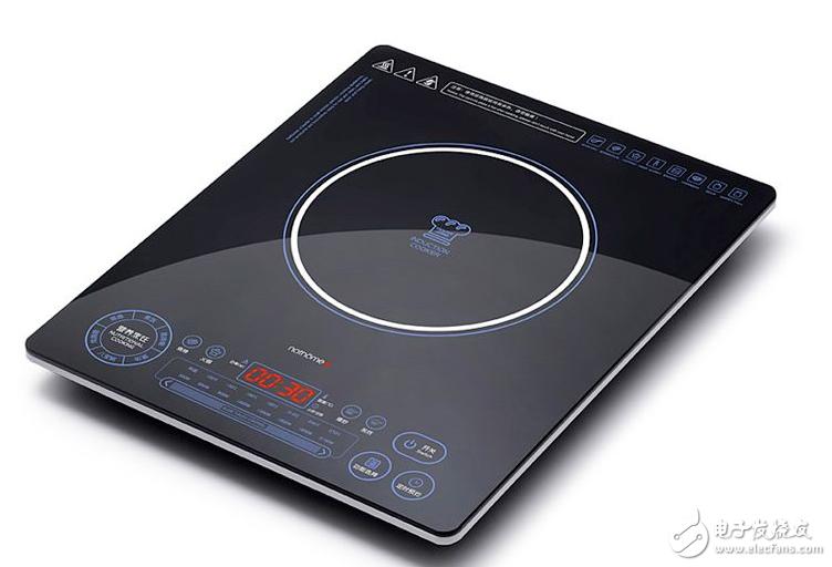
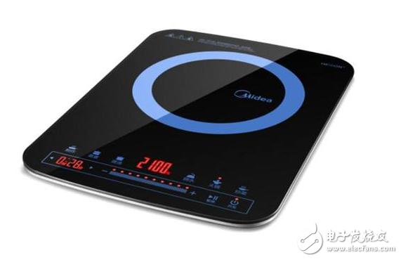
Almost every family now uses induction cookers. The principle of the induction cooker is the phenomenon of electromagnetic induction, that is, the alternating magnetic field that changes direction by the alternating current is generated by the alternating current, and the eddy current will appear inside the conductor in the alternating magnetic field (the reason can be referred to the Faraday's law of electromagnetic induction). It is caused by the vortex electric field pushing the carriers in the conductor (electrons in the pot are not iron atoms); the Joule heating effect of the vortex current heats the conductors to achieve heating.
The basic principle of induction cooker capacitive touch sensing control technology
The so-called capacitive touch-sensitive control technology, the core is to use the relaxation oscillator to generate a sine wave of hundreds of kilohertz, and then add this sine wave signal to each spring conductive disk, when the user's finger touches the conductive disk (even There are panels separated, but for high-frequency signals, glass, ceramic, plastic and other material panels are still equivalent to conductors), which is equivalent to connecting a capacitor to the ground of the spring conductive disk, using the characteristics of the capacitor through the straight line. The high frequency signal is divided by the capacitor and the signal level on the spring disk will decrease.
This reduced signal voltage is applied to the threshold detector (or sent to the internal circuitry of the comparator for processing to reverse the output level of the corresponding output), which produces a touch/no touch signal.
There are two main types of induction cookers that use capacitive touch-sensitive control technology on the market.
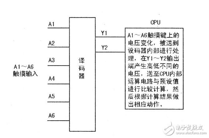
The first is to apply a sine wave of hundreds of kilohertz generated by the relaxation oscillator to each of the function key spring pads. Each function key is connected to the input end of the comparator, and is compared by the internal circuit of the comparator, and the high and low level changes are realized at the output end, and one button corresponds to one I/O port, and each I/O port is respectively The high or low two different levels are used to indicate whether the button is on or off. The advantage of this method is that it does not need to change the hardware and software of the previous main system, and only needs to do a single keyboard board to realize the touch button function, which is very suitable for the old product transformation, so this method is more common on the earlier induction cooker. The working principle is shown in the figure below.

The second way is that the keyboard input interface is the same as the first one. The difference is that the output uses SPI, IIC, UART or a limited number of I/O ports to output the encoded data. The advantage of this method is that it is required. The I/O port is small, and the output generally only needs 2~3 I/O ports to realize data transmission. The working diagram of this control method is shown in the figure below, but it is rare in the induction cooker.

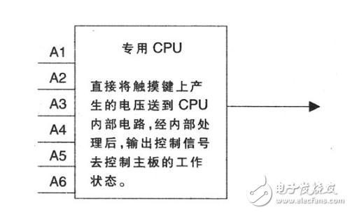
The third way is to adopt a highly integrated touch sensing product solution. The solution needs to use a dedicated CPU chip to directly send the voltage change generated by the touch key to the internal circuit of the CPU, and then control the working state of the main board of the induction cooker after being processed by the internal circuit. The working diagram is shown in FIG. 5 . This solution greatly simplifies the circuit structure and reduces product cost.

Technical Analysis of Induction Cooker Maintenance
First, burn igbt or fuse
If the current fuse or igbt burns out, the part cannot be replaced immediately. It must be confirmed that the following other parts can be replaced under normal conditions. Otherwise, the igbt and the fuse will burn out.
1. Visually see if the current fuse is blown
2. Check if igbt is broken down:
Use the multimeter diode file to measure the "e" of the igbt; "c"; whether the "g" is broken between the three poles.
(1): "e" pole and "g" pole; "c" pole and "g" pole, both positive and negative tests are not conductive (normal).
(2): The multimeter's red pen is connected to the "e" pole, and the black pen is connected to the "c" pole with a voltage drop of about 0.4v (the model is gt40t101 and the three poles are all unreachable).
3. Measure whether the transformer is broken or not. The normal state is as follows:
Use the multimeter resistance file to measure the secondary resistance of the transformer to about 80ω; the initial is 0ω.
4. Is the rectifier bridge normal (tested with a multimeter diode):
(1): The multimeter's red pen is connected to "-", the black pen is connected to "+" with a voltage drop of about 0.9v, and the reversal has no display.

(2): The red pen of the multimeter is connected with "-", and the black pen is connected to the two input terminals with a voltage drop of about 0.5v, and the reversal has no display.
(3): The black pen of the multimeter is connected with "+", and the red pen is connected to the two input terminals with a voltage drop of about 0.5v, and the reversal has no display.
5. Check capacitance c301; c302; c303; whether it is damaged by heat. (If the damage has been deformed or melted)
6. Detect whether the chip 8316 is broken down. Measurement method: measure 8316 pins with a multimeter, and require 1 and 2; 1 and 4; 7 and 2; 7 and 4 cannot be short-circuited.
7. Whether the thermal switch insulation protection at igbt is damaged.
Second, the button does not work well
The detection of poor button operation is to measure whether the cpu line is broken. Using a multimeter diode file to measure the cpu pole and the ground terminal, there is a voltage drop of about 0.7v. The multimeter's red pen is connected to the "ground", and the black pen is connected to the "cpu every pole line." Otherwise, the cpu line breaks down.
Third, the power can not meet the requirements
1. Short circuit of the coil disk: the inductance of the test coil disk: the psd coefficient is l=157±5μh, and the pd series is l=140±5μh.
2. Whether the distance between the pot and the coil disc is normal.
3. Whether the pot is the designated pot.

Fourth, check whether the various gas parts are loose and complete.
Inspection of bad conditions after assembly:
1. No heating: Check if the transformer is broken.
2. Long sound after plugging in: Check if the temperature switch terminal is plugged in well.
3. Can not be turned on: Check if the thermistor terminals are plugged in well.
4. No small object detection (no alarm): Check if the resistance r301~r307 is normal.
R301~r302 is 68kω, r303~r306 is 130kω, r307 is 3.0kω
5. The fan does not turn; check if the transistor q2 is burnt out. (Generally, the triode pin has been yellowed; it can also be measured with a multimeter diode)
Industrial Main Board Cable:SCSI,D-SUB,DVI,Wire to Wire ,RJ45...
There are five types of main board power line interface, and different external devices correspond to different interfaces. Different interfaces and their connecting pins are also different. For example, the pin of the main power supply is 24 pins, and the hard disk drive is 5 pins.
1. 20pin + 4Pin interface: it is a common interface combination, in which 20pin is the main power interface and 4Pin is the auxiliary power supply interface.
2. 5pinsata interface: special interface for power supply of hard disk and optical drive.
3. 6pin? PCI? Express connector: a special interface for independent graphics power supply.
4. 4Pin connector: it is a kind of floppy disk power connector, which is used to power the floppy drive equipment.
5. 4Pin power interface: optical drive, old IDE hard disk and peripheral hardware power supply interface.
Industrial Main Board Cable
ShenZhen Antenk Electronics Co,Ltd , https://www.atkconnectors.com
