
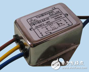
LOAD termination load, is the emergence, N is connected to the zero line, L is connected to the live line, the three E on the right side are grounded, and the N is connected to the zero line L. Is the power input.
The connection method is as follows: input L is connected to 1, N is connected to 2; output L' is connected to 3, N' is connected to 4; the ground wire can be grounded.
A power filter is a filter circuit consisting of a capacitor, an inductor, and a resistor. It is also known as a "power EMI filter" or an "EMI power filter." A passive two-way network that has a power supply at one end and a load at the other end. . The principle of the power filter is one - impedance matching network: the greater the impedance adaptation between the input and output sides of the power supply filter and the power supply and load side, the more effective the attenuation of electromagnetic interference is. The filter can effectively filter out the frequency of a specific frequency in the power line or a frequency other than the frequency to obtain a power signal of a specific frequency or eliminate the power signal after a specific frequency.
The power supply noise filter shown in the figure is a passive network with bidirectional suppression performance. Insert it between the AC grid and the power supply, which is equivalent to adding a blocking barrier between the EMI noise of the two, so that a simple passive filter acts as a two-way noise suppression, thus enabling various electronic devices. It has been widely used.
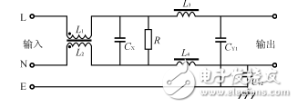
Figure Basic circuit diagram of the power filter
1. There is no electromagnetic coupling path in the power filter.
1 power input line is too long;
2 The input and output lines of the power filter are too close.
Both of these are incorrect installations. The essence of the problem is that there is a significant electromagnetic coupling path between the input wire of the filter and its output wire. In this way, the EMI signal present at one end of the filter escapes the suppression of the filter and is directly coupled to the other end of the filter without the attenuation of the filter. Therefore, the filter input and output must be effectively separated first.
In addition, as the above two types of power supply filters are installed inside the device shielding, the EMI signal on the internal circuits and components of the device will be directly coupled to the outside of the device due to the EMI signal generated by the radiation on the (power) terminal of the filter. Going, the device shielding loses the suppression of EMI radiation generated by internal components and circuits. Of course, if there is an EMI signal on the filter (power supply), it will also be coupled to the components and circuits inside the device due to radiation, thereby damaging the suppression of the EMI signal by the filter and the shield. So it won't work.
2, can not bundle the cable
In general, when installing a power filter in an electronic device or system, be careful not to bundle the wires between the filter (power) end and the (load) end when strapping the device cable, as this is undoubtedly exacerbated. The electromagnetic coupling between the input and output of the filter severely destroys the ability of the filter and device shield to suppress EMI signals.
3, try to avoid using long grounding wire
It is advisable to connect the output of the power filter to the inverter or the motor with a wiring length of not more than 30 cm.
Because an excessively long ground line means a large increase in grounding inductance and resistance, it can severely damage the filter's common mode rejection. A better method is to secure the shield of the filter to the housing at the power inlet of the unit with metal screws and star spring washers.
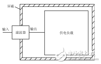
Figure Filter installation method
4 , the power filter input line, output line must be pulled apart
The input and output lines of the power filter must be pulled apart. Avoid paralleling to avoid reducing the filter performance.
5, the power filter housing and the chassis must be in good contact
The inverter-specific filter metal case and the chassis must ensure good surface contact and connect the ground wire.
6, the connection line of the power filter should use twisted pair
The input and output connection lines of the power filter are preferably shielded twisted pairs, which can effectively eliminate some high frequency interference signals.
Stylus Pen Tip,Stylus Pencil Tip,Carbon Fiber Pen Tip,Carbon Fiber Stylus Pen Tip
Shenzhen Ruidian Technology CO., Ltd , https://www.wisonen.com