
MF-TDMA satellite network is composed of ground master station, standby master station, network control center, many slave stations, satellite repeaters and other units. The main business of the system is voice, data, video, but the communication capacity of each satellite station is different. Each ground station acts as the calling or called party and applies to the network control central station for satellite channel resources. Therefore, the satellite network resources and information must be effectively managed and deployed so that it can cope with various complex emergencies and adapt to applications Changes in tasks, the network itself and external conditions ensure that the satellite communication network operates stably, reliably, continuously and efficiently.
The RaTIonal Rose tool is a powerful tool developed by the American RaTIonal company for analyzing and designing object-oriented systems. It can help model first and then perform functional tests to ensure that the system has a reasonable structure and operates normally. The RaTIonal Rose tool supports visual development of test case models. Combined with the actual situation of satellite networks, it mainly conducts business modeling, analytical modeling, and design modeling, and then completes use case-driven, iterative, and incremental testing tasks.
It mainly introduces the test methods of several important design elements in the satellite network, and discusses and studies the TDMA technology system required by the networked service transmission through simulation modeling.
1 Network model composition and business process
1. 1 Network model
When networking applications in MF TDMA mode, the master station sends TDMA reference signals and serves as the time reference for all stations in the network. A backup master station is used to take over the work of the master station when the master station fails. The general service station takes the master station as a reference and sends information in the time slots allocated to the own station according to the time slot table issued by the master station. The realization model of satellite communication network is shown in Figure 1.
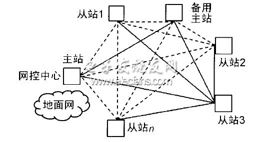
Figure 1 The architecture of a satellite network semi-physical simulation network
Design methods such as frame synchronization design, call service volume adjustment, and RF link power adjustment in network operation are key technologies for efficient network operation. To this end, establish the following test model and test process.
The tester uses the sequence diagram to obtain the information required by the test script. The test process includes 4 steps:
â‘ Convert the sequence diagram into a flowchart; â‘¡Identify the path to be tested from the flowchart, first identify the entry-exit path, so that all decision branches will be adopted at least once, and each tracked path becomes a test case; â‘¢ Identify special anomalies, that is, used to develop test cases to test the anomaly handling related to the implementation under test; â‘£ Identify the inputs and states required to adopt a specific path, and will follow the path when all path conditions are met The test case defines the specific inputs and states that need to satisfy the path conditions. Finally, the expected results of each test instance are determined, and the test package is completed. The obtained test package can be implemented in a user test driver using a specified scripting language.
1. 2 MF TDMA system timing synchronization model
Timing is a key issue in TDMA systems. It provides a time base for system operation and is the basis for initial acquisition and synchronization maintenance.
Initial acquisition refers to the process of ensuring that the earth station can correctly enter the designated time slot when it starts to transmit a burst, without entering the other time slot and causing interference.
1. 3 Apply for voice progression model
Establish a duplex user model that can be used as both the caller and the called party. When calling, the user makes a call request based on the loaded service; while being called, the user needs to make the necessary response to the caller to ensure the establishment of the call link. The entire test process is as follows: The end user station sends a call request Frame and obtain the channel allocation frame. After the application is successful, the channel allocation package is passed to the user process. If the application fails, the support process is notified of the failure. These processes are the test paths identified by the flowchart.
1. 4 RF and link model
The radio frequency model includes two parts: the upstream radio frequency and the downstream radio frequency. The former mainly processes the transmission power of the ground station, and the latter mainly determines the bit error problem. Here, the uplink is restricted, that is, the application path can only be transmitted to the network control center; on the downlink, it is mainly to confirm whether the signal power from the satellite module reaches the signal-to-noise required by the radio frequency module connected to this link Than, if it is, then accept it, otherwise discard it. All frame transmissions must pass through the delay of a satellite channel and meet the power control requirements of the receiving station.
Configure a value for the burst signal-to-noise ratio of the modulator of each station, and this value is used for transmission power control. The remote station reports the signal-to-noise ratio of the reference burst they received from the control station to the control station. A field of the TDMA frame header is used for this purpose. The control station adjusts its transmission power level to reduce the signal-to-noise ratio. The ratio is controlled within a desired range. Each remote station also adjusts their upstream power so that their bursts have the same signal-to-noise ratio as the reference burst when they are received.
2 Test model simulation
2. 1 Network synchronization parameter setting
The synchronization maintenance adjustment interval time refers to the period in which the burst transmission time needs to be adjusted in order to maintain synchronization of the entire network. The more frequent the adjustment, the smaller the impact of various errors on synchronization maintenance, and the greater the cost of the adjustment process itself; conversely, the greater the impact of various errors on synchronization maintenance, and the overhead of the adjustment process itself The smaller. Therefore, compromises should be considered in system design.
The synchronization maintenance error is the accuracy that can be achieved at the moment of burst transmission within a certain synchronization maintenance adjustment period (synchronization maintenance adjustment interval time). It is related to errors caused by satellite drift, errors caused by clock stability, logic circuit jitter, and adjustment accuracy.
2. 2 Voice parameter settings
The network structure of the system is a mesh network, and the system parameters are described as follows:
①Each station in the system supports a maximum of 20 voice channels; the rate of each channel is 2 400 bps; ② The transmission time interval of each station follows the exponential distribution of t = 500 s, and the length of the transmitted data packet follows the average k = 1 240 bit Poisson distribution, the total number of stations is 100, the channel retransmission is 3 times, and the retransmission time follows an exponential distribution; ③Satellite delay time is 0.27 s; ④Central station is 1 network control station, service rate is 9 600 bps; ⑤ Assuming that the central station receives the data packet of the small station, it is a successful call; ⑥ The number of stations gradually increases. Among them, the connection delay refers to the time from when a call is generated to when it is connected to prepare for a call.
2. 3 Power adjustment parameter setting
The establishment of the power adjustment mechanism requires a coordinated response of the parameters of each station in the satellite network. To this end, the special test process established by the RaTIonal Rose tool is: Identify the input data and status required to adopt a specific path, when all path conditions are met Follow this path. If it is not satisfied, an alarm will be given and a feasible index will be prompted. All the data defined in the test cases require specific input data and status that meet the path conditions. The following parameters can be set in the power adjustment test case.
(1) SNR parameter setting
Define the signal-to-noise ratio of three reference bursts in the parameter file of each station to achieve the desired link quality:
The minimum signal to noise ratio (Minimum Es / No) is 70; the moderate signal to noise ratio (Moderate Es / No) is 100; the maximum signal to noise ratio (Maximum Es / No) is 130.
In addition, a downlink control value is defined in the control station parameter file. The significance of this parameter is: How many remote stations receive the control station's burst signal quality is lower than the expected value can cause the control station to increase the transmission power.
(2) Adjust the transmission power in rain area
If the control station detects that it cannot increase the power level to the desired value, it will set a flag in the reference burst to tell each remote station. The remote station then freezes its power level. They read the latest power level value from the site's parameter file.
(3) Update, sort, and categorize
If the control station is in the rain zone, the uplink transmission attenuation of the reference burst will increase, and each remote station will report that the reception quality has deteriorated. Due to different local conditions, the signal quality of some stations will be lower than the threshold of the minimum signal-to-noise ratio (Minimum Es / No). When the number of stations with poor received signal quality exceeds the value of the downlink control parameter (Down Linkpower Control) of the control station, The control station increases the transmit power level under the control of the power control mechanism. When the downlink control value is small, the control station will react earlier and the power level will increase immediately.
The remote station reports the actually received signal-to-noise ratio. "Maximum, moderate and minimum signal-to-noise ratio" as the parameters of the control station, the control station compares the reported value and the control parameters, and classifies the values. "Maximum, moderate and minimum signal-to-noise ratio" as the parameters of this station are classified by the remote station and report the results to the control station.
Audible and visual alarm is set up to meet customers' special requirements for alarm loudness and installation location. At the same time, two alarm signals, sound and light, are issued. Special fields: iron and steel metallurgy, telecommunication towers, hoisting machinery, construction machinery, ports, transportation, wind power generation, ocean-going ships and other industries; it is an accessory product in the industrial alarm system.
emergency alarm,Audible Visual Signals,Visual Alarm devices,sound and light siren,visual alarm system
Taixing Minsheng Electronic Co.,Ltd. , https://www.msloudspeaker.com