In recent years, the supply of industrial robots has shown an upward trend in most industries. The service robot has a short history. The main differences in function are reflected in two aspects: one is communication with people; the other is to replace part of the work in a complex environment.
The term "robot" first appeared in the "Universal Robot of Rossom" by the Czech science fiction writer æ° å…‹ in 1920. The original text was "Robota" and later became the "Robot" in English. The more scientific definition was proposed by Japanese scientist Mori Masahiro and Hetian Zhou Ping in 1967: "Robot is a mobile, individual, intelligent, versatile, semi-mechanical, semi-human, automatic, slave, and other seven characteristics. Flexible machine."
The International Robotics Federation divides robots into two categories, industrial robots and service robots. The industrial robot is "an automatically controlled, programmable, multi-function actuator with three or more programmable axes for industrial automation, which can be fixed or mobile." The service robot is “a semi-autonomous or fully autonomous robot that can perform services that are beneficial to human health, but does not include equipment for productionâ€. As can be seen from the definition, the standard of classification is the application of the robot.
The general robots are composed of mechanical structure, control drive system, sensing system, and interactive system.
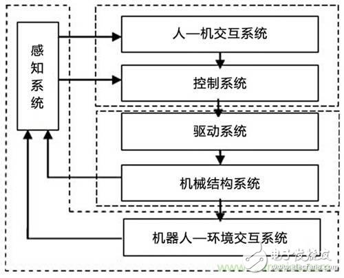
Figure 1 System structure of a general robot
In the future, the world robot market combined with industry and service applications will become a trend. In order to meet the needs of the market, many robot solutions come out. For example, the robot brain uses Rockchip RK3288 as the main platform and the 4-core Cortex-A17 processor. With a clock speed of 1.8GHz, the latest generation of GPUs (Mali-T764) can successfully support high resolution (3840X2160) display. The part of the robot body uses the NXP LPC54102 as the control part, and the driver part uses the Toshiba TMPM375FSDMG chip to achieve proper FOC control.
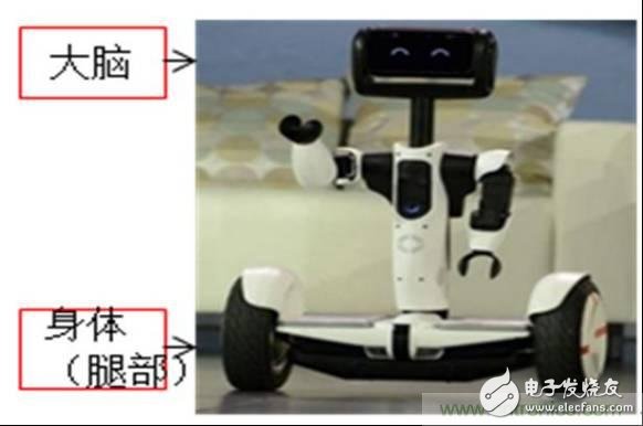
First, a new generation of robot brain solutions based on Rockchip RK3288
1, functional block diagram
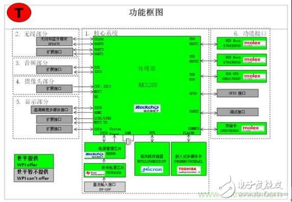
2, the function description
1 RK3288 minimum system
2 Support WIFI & BT function
3 integrated HDMI, USB, SD card, external expansion port
3. Important features
1 4 core Cortex-A17 processor, clocked at 1.8GHz, embedded with the latest generation of GPU (Mali-T764) can successfully support high resolution (3840X2160) display
2 compliant with 96Boards interface definition
Second, the wheeled robot solution based on NXP LPC54102 and Toshiba TMPM375FSDMG
1, functional block diagram
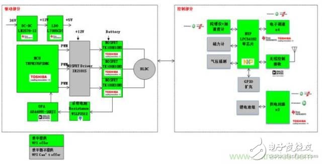
2, the function description
1 It can realize the direction of motion of the robot by controlling the yaw angle by remote control.
2 can control the speed and distance of the robot
3. Important features
1 Using a nine-axis sensor to complete the motion control of the robot through the attitude algorithm
2 The robot driver board uses Toshiba TMPM375FSDMG to achieve proper FOC control
Third, based on NXP low-power Bluetooth control robot design
The Bluetooth® Low Energy (BLE) controlled robotic reference design was developed using the FRDM-KW40 board and the Pololu Zumo robot and can be controlled via the mobile app. The BLE-controlled robot is based on the KineTIs KW40Z System-on-Chip (SOC), which includes an ARM® Cortex® M0+ processor with a 2.4 GHz radio for BLE and 802.15.4. It is implemented using the HID over GATT configuration file and is used as a human interface device. Features provided by the software include: BLE data to mobile app transfer, motor control and battery monitoring, and more.
1. Low-power Bluetooth controlled robot system block diagram
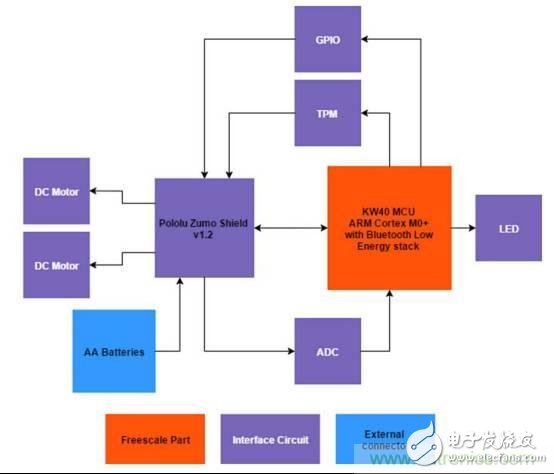
2. Low-power Bluetooth controlled robot reference design features
These include NXP's ultra-low-power KineTIs KW40Z SoC, which provides Bluetooth® Smart/Bluetooth® Low Energy (BLE) v4.1 and/or IEEE® 802.15.4-2011 for portable, ultra-low power embedded systems. RF connection
Developed with the KineTIs Software Development Kit (SDK), providing comprehensive software support for KineTIs MCUs, including a hardware abstraction layer (HAL), drivers for each MCU peripheral, connection stack, middleware, real-time operating system, and application examples. Designed to simplify and accelerate application development based on Kinetis microcontrollers.
3, support devices
KW40Z: Kinetis® KW40Z-2.4 GHz dual mode: BLE and 802.15.4 wirelessly connected microcontroller (MCU) based on ARM® Cortex®-M0+ core
The KW40Z is a highly integrated, single-chip device that enables portable, ultra-low-power embedded systems with Bluetooth® Smart/Bluetooth® Low Energy (BLE) v4.1 and IEEE® 802.15.4-2011 RF connectivity. Applications include portable medical devices, wearable sports and fitness equipment, AV remote controls, computer keyboards and mice, game controllers, access control, security systems, smart energy and home networking.
The KW40Z MCU integrates a 2.4 GHz transceiver supporting multiple FSK/GFSK and O-QPSK modulations, an ARM® Cortex®-M0+ processor, 160 KB flash and 20 KB SRAM, BLE link layer hardware, 802.15.4 packet The processor, hardware security and peripherals are optimized to meet the requirements of the target application. The KW40Z has enough on-chip memory to run both the Bluetooth Low Energy stack and the IEEE 8021.5.4 MAC/PHY for multimode applications.
characteristic
Multi-protocol radio:
Compliant with 2.4 GHz Bluetooth Low Energy V4.1
Compliant with IEEE Std. 802.15.4-2011 standard
Typical Receive Sensitivity (BLE) = -91 dBm
Typical Receive Sensitivity (802.15.4) = -102 dBm
Transmit output power can be set from -20 dBm to +5 dBm
Kernel and memory aspects:
Up to 48 MHz ARM® Cortex-M0+ core
On-chip 160 KB flash
On-chip 20 KB SRAM
Low power consumption, operating voltage range:
9 low power modes, optimized power supply based on application requirements
Typical Receive/Transmit Current (DC/Supported DC): 6.5 mA / 8.4 mA
Bypass voltage: 1.71V to 3.6V
DCDC converter step-down configuration: 2.1V to 4.2V
DCDC converter boost configuration: 0.9V to 1.795V
Analog module:
16-bit analog-to-digital converter (ADC)
12-bit digital-to-analog converter (DAC)
6-bit high speed analog comparator (CMP)
safety:
AES-128 Accelerator (AESA), True Random Number Generator (TRNG)
Support software:
BLE host stack and configuration file, 802.15.4 MAC and SMAC
Kinetis® Software Development Kit (SDK)
FreeRTOS kernel and bare metal non-preemptive task scheduler
summary
The application in the dangerous environment and becoming the assistant of people's work and life are the two major trends in the future development of robots. Of course, it is quite challenging to make the robot work like a human being and become an assistant.
First, there is a need to address the robot's ability to move in complex environments. Second, enhance awareness and decision making. For unmanned vehicles, speed is one of the main features. How to make a proper response to the changing environment at high speeds determines the safety of unmanned vehicles and is one of the biggest obstacles to the industrialization of unmanned vehicles. As we all know, the way of machine perception and decision-making is completely different from that of human beings. Human perception has strong selectivity. The principle of foreground, post-dynamic, post-dynamic, and first-order normal can make people quickly in complex environments. Find the target. This ability is very worthy of robot research and emulation.
In short, the demand for robots in the market has continued to rise in recent years. Governments, relevant research institutions and enterprises have attached great importance to the development of robotics, invested a lot of resources, and the development of robotics has shown a good momentum. The high-tech problem in robotics has inspired many outstanding robot R&D teams around the world to innovate and forge ahead. In the future, robots will become an indispensable tool in daily life, bringing people a more comfortable and convenient life.
Basic Features
1. The terminal has universal mounting feet so that it can be installed on U-rail NC 35 and G-rail NC32.
2. The closed screw guide hole ensures ideal screwdriver operation.
3. Equipped with uniform accessories for terminals of multiple cross-section grades, such as end plates, grouping partitions, etc.
4. Potential distribution can be achieved by inserting a fixed bridge in the center of the terminal or an edge-plug bridge inserted into the wire cavity.
5. The grounding terminal and the N-line slider breaking terminal with the same shape as the common terminal.
6. Using the identification system ZT, unified terminal identification can be realized.
7. The rich graphics enhance the three-dimensional sense of the wiring system.
Din Rail Terminal Block,Din Rail Fuse Terminal Block,Din Rail Busbar Terminal Block,Din Rail Power Terminal Blocks
Sichuan Xinlian electronic science and technology Company , https://www.sztmlch.com
