
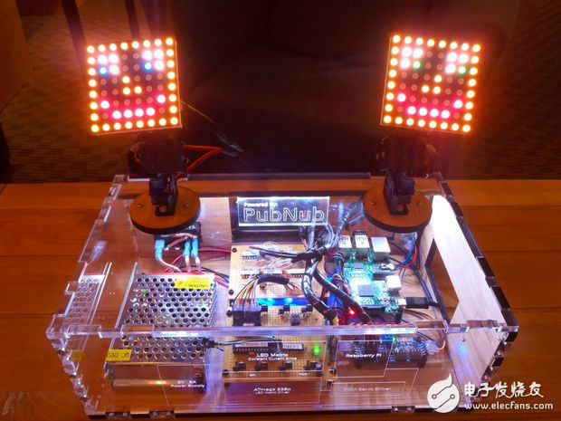
Secure, reliable real-time data streams are two essential things in the Internet of Things. After seeing a lot of hardware such as "press here, the lights will light up", I and a friend want to do something more interactive in the manipulation of it but barely feel the existence of the data stream. Sexual things! So, we decided to create a model that can control the "things", imitating the motion of your hand and displaying the motion of the finger based on the color. I hope that with the help of this article, you can make your own hardware products.
A conceptual overview and some more in-depth understanding can be found in the PubNub blog. The complete code can be found in the GitHub repository, and the "The LED matrix driver circuitry" article on Instructable details the LED matrix. How the drive circuit is written.
Step 1: Parts and tools
There are a lot of small pieces to solve this problem, here are some main things to try.
Parts and fragments
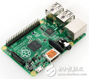
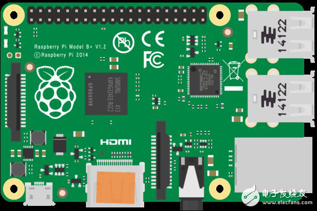
· Raspberry Pi---V1 type B + is used here
· Jump motion controller
· 5V power supply
· I2C capable PWM driver
· 4 mini servos - the cheap TowerPros.
· 4 micro servo bearings
· LEDs and current limiting resistors – for visual effects, but not necessary.
· Project Chassis --- This one is laser cut Ponoko.
· Screws, bolts, nuts, paper clips - and other similar things that are fixed together.
· Cable wrap - in order to keep the wires clean and tidy.
· Power outlets, switches and cables -- so that power can be transferred.
· Toggle switch --- for selecting the servo output mode
· Small button ---- used as R丕 restart/shutdown button
· RGB LED + 2 × 470 ohm resistor - restart / shutdown indication
· Supports --- Easy to install a variety of devices, these are many on Amazon.
· Mounting wires --- for connection.
The RGB matrix sits on top of the servos using a custom driver. This part of the project is quite advanced and is described in the Instrucable.
Software and services
· PubNub - Data Streaming Service. Free sandbox mode development!
· Java SE --- JDK8 - Be sure to get the correct version for your operating system.
· Jumping Sports Showcase and Java SDK - Be sure to get the correct package for your operating system.
· PubNub Java SE SDK --- This requires access to the project library directory
· Java IDE - use your favorite, such as JGrasp, IntelliJ in NetBeans, or Eclipse
· Project Source Code Repository - hosted on GitHub
Raspberry Pi
· PubNub Python library - This is a more in-depth guide on the Raspberry Pi.
· Internet connection - either WiFi or Ethernet. If you can ping Google, then it is a good place to go.
Tools and the like
· Computer - write code, view Instructables, etc.
· Electric drill + drill / drive - drill holes, twist screws, etc.
· Dremel rotary cutter - for cutting holes in the chassis. . . Some friends may not have this need.
· Hot glue gun – Is there any other bonding method?
· Soldering iron + soldering - Do not inhale fumes!
· Laser cutting machine - Again, I used a service, but you can DIY if you have your own machine laying around.
· Screwdrivers, pliers, etc. These things you should have now!
Step 2: Project Preview
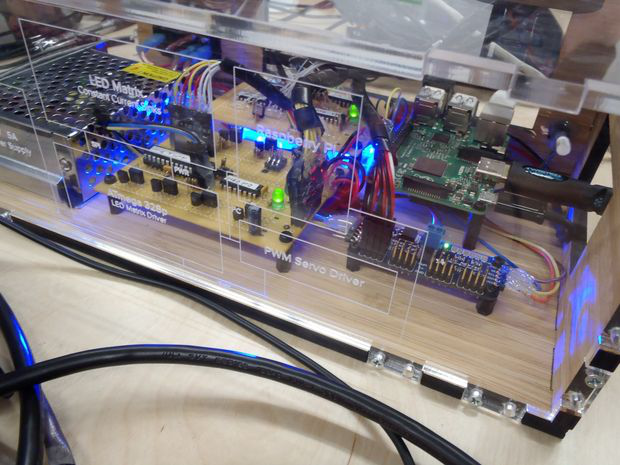
The top design is divided into three main components:
1. Computer and jump motion controller ---- used to publish data to the Internet.
2. The Raspberry Pi in the "Box" - --- Subscribe to data from the Internet.
3. PubNub - The communication layer securely connects these things.

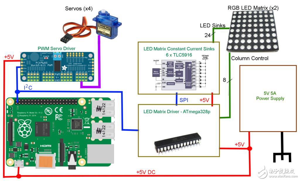
The computer part is very simple, but there is more to it in the "box". . .
1. Raspberry Pi - the main controller, using I2C bus communication
2. ATMEGA328P matrix drive circuit - receive commands through the I2C bus, control 28 × 8 matrix RGB
3. Circuit based on TLC5916 LED -- controlled by ATMEGA328P, sink LED matrix current
4. Adafruit PWM driver ---- drive 4 servos to receive commands via I2C bus
5. 5V, 5A power supply
First, we need to set up the user's computer to facilitate the use of the jump motion controller.
Step 3: Java and Jump Motion Controller Settings

Java settings
We will use the Java SDK's jump motion controller, so we only need to install the Java Development Kit, which includes the Java runtime environment. This is very simple, just choose the right package for your operating system.
Instead of creating an installation package, it is source code that runs directly from the Java IDE. This allows you to manipulate the code yourself, modify it, and learn! After installing the JDK, you need a good IDE (that is, an integrated development environment). Some common ones are IntelliJ in Eclipse, and NetBeans. You can choose one. The libraries created by each user are different, so you must refer to the documentation to learn how to set up a new project!
Java source code
Only one java file needs to run the code, but the jump movement and the PubNub Java library must also be installed. . . GitHub's project library contains some very necessary Java files.
Leap settings
Setting a jump can be tricky, and it will vary from system to system, not step by step. This is not to tell you how to do it, but to guide you to the corresponding article. No matter where you don't understand, you can always ask for help.
1. Download SDKs, drivers, and applications for jumping sports.
2. Install the Jump app, which will install any necessary drivers and processes.
3. Run the jump motion diagnostic visualization tool to ensure the jump is working.
4. Browse the Java SDK documentation, especially the setup project.
PubNub settings
The final step is to download the PubNub Java SDK. The documentation page will talk about how to add libraries to your Java project.
Step 4: Java source code
If you are not interested in Java code, you can skip this step; however, you will at least need to put your personal PubNub key into the code to work for it! The source code can be viewed on GitHub.
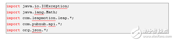
Here are some of the entry requirements. If this goes wrong, it is likely that the SDK library is not installed correctly.
To make the project implement Runnable, it is critical that all jump activities work on their own threads. We first set up the project as the main, the implementation of the Runnable interface and the initialization of global variables for later use. The main thing to note is the global variable "CHANNEL" and a pair of main claim keys.
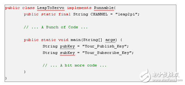
These strings are the only values ​​that can be changed. The channel name can be left with the default "leap2pi" or some other alphanumeric value. Use PubNub to talk to more than one channel to talk about everything, so use a unique name to prevent crosstalk between different projects! Publish and subscribe keys, when you sign up for a PubNub account with unique personal identifiers to guarantee their security and privacy, these keys prevent others from talking to your channel(s), please note that there may be specific use of characters The string "leap2pi" instead of the constant "CHANNEL," and in all of these cases should change some parts of the code.
The jump motion captures 300 frames per second. At each frame, we have the opportunity to get a lot of information, such as finger straight, pitch, yaw and gestures. The value returned by the leap and yaw (the wrist) is radian, which doesn't help us too much. We want these values ​​to be converted to the format accepted by the PWM driver in the box. We first convert the radians to degrees and then to between 150 and 600, which is equivalent to a servo (500 - 2000 us) typical operating range of acceptable servo PWM values ​​represented by a 12-bit servo drive.
The basic formula is US 2500/(2^13-1)* (servo minimum/maximum pulse width), so [500,2000] we map to [150,600]. . . . . . Probably in the code, these conversions are handled by the following methods.
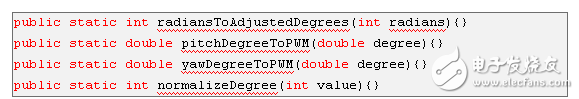
Also, please forgive the code in the incorrect servo and PWM terminology. . . . . . Not every production enthusiast is an expert in these disciplines!
The best way to ensure that your code is working is to load the PubNub Debug Console. From here, you can enter the channel name, just like the publish and subscribe keys. Click on "Subscribe" and when the action jump controller is running the Java code, the published data should be displayed in the message box.
Step 5: Raspberry Pi installation
With the work of Java code, it's time to set up Raspberry Pi subscription data and use it to drive LEDs and servos. In the Internet connection that has been configured with the Raspberry Pi, it can be WiFi or Ethernet, but this part needs you to complete! If you need help, you can look it up on PubNub (someone wrote it some time ago). In addition, you can use the monitor and keyboard to complete any step directly on the Pi, or log in remotely using SSH. Either way, the ultimate goal of the project is to have a standalone, headless, installer that automatically runs the files needed to start.
The first step is to install the PubNub Python SDK.
Open the terminal and install the following:
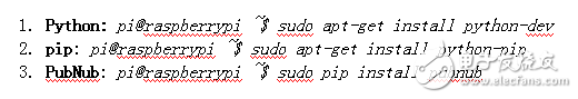
Well, this is very simple! Now we need to get a copy of all the files in the skin directory of GitHub's repository. The easiest way to do this is to use Git clone repo and then remove other unwanted things:
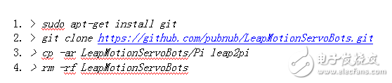
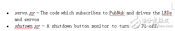
Now, the contents of the leap2pi directory should be the same as the files in the GitHub repository Pi directory. Finally, we want the Python script to run at startup. Here are two Python scripts to run:
This is very simple, we only need to edit a Linux system file as the root user. First, make sure the script is executable and then open the rc.local file for editing.
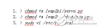
You can use any editor you like, I prefer VI. The last line of the file should be "exit 0", which is the initialization of the clean exit and hit terminal that is allowed to use the file. Any number of commands can be added here as long as they run the last "exit" command.
Insert the following "exit 0" command directly above:
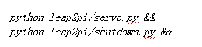
Save the file, exit, and after the boot, Pi will automatically run these scripts. The "&&" section ensures that every command runs. If you leave the off, the bash terminal will always load, so you will be locked in your personal information indefinitely!
Step 6: Connection between Raspberry Pi and Servo Drive
The Raspberry Pi can be used to drive the servo system directly, but it takes a bit of work. There is a dedicated PWM channel, but we need 4 wires. Because it can be virtualized in software, but this is not a simple matter. As a computer, the Raspberry Pi is much better at the higher level than the low level. This step you can of course use any PWM driver, but I use this 16-channel, 12-bit driver in the form of Adafruit. Yes, this is a little over, it is very easy to program the ATtiny24 operating 4 servos to communicate via the I2C bus. You can create your own, but it may be beyond the scope of this guide.
There are many tutorials online that can help you use this motherboard, you will need some extra source code files. These can be found in the directory where the source code library's named file is "Adafruit". . . . . . "It will tell the Raspberry Pi how to communicate with the PWM driver.
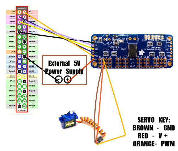
Connecting the Raspberry Pi board is easy. Pins 3 and 5 are found on the Raspberry Pi I2C line, but in this case, the I2C communication channel needs to be opened, remember to check. An important input pin is labeled "OE", which is an active-low "output enable" pin. When this pin is held low, the servo system is enabled. It can be connected directly to ground or drive another One end IO pin. In this project, the ATMEGA328P matrix driver circuit is also connected to the R-segment using the I2C data line.
In this figure, the servo is attached to channel 1 PWM driven. In the project, set a steering gear like this:
Step 7: Closer look at servo.py
Python code to control the servo is very simple, as long as you understand Python. Personally, I don't really like this language, but this is a digression. You can view this copy of the servo.py file on GitHub.
Just like in Java code, you need to post your personal PubNub, subscribe to the key here, and the name of the communication channel.
The Raspberry Pi will do the following to do the following:
1. Reset the AVR matrix drive circuit.
2. Initialize PubNub with your key.
3. Subscribe to the PubNub channel "leap2pi".
4. Forever loop, check the output mode switch (multiple checks in one minute).
At the bottom of the system, all the work is done in the PubNub repository. This will call all the operations, we only need to specify some callbacks -- this is the function that needs to be called when the event occurs.
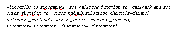
The connection callback should be obvious (connect, reconnect, etc.), but a callback that doesn't have a lot of work properly named "callbacks". This function is actually doing these things from receiving a subscription channel. As mentioned above, the box has a pair of output modes that are selected for sliding switch selection of several IO lines.
• Mirror - the robot will reflect your movements; therefore, your left hand reverse control robot
• Disabled - the servo system will stop responding
• Clone - the robot will clone your action; therefore, your left hand directly controls the left robot
The logic of these modes is also handled by the callback function in the I2C driver report.
It is worth noting that the only item in this file is to use GPIO pin 4 as the output. This pin drives the MOSFET and connects to the gate of the blue LED ground array. This pin enables the PubNub connection, such an LED as a connection indicator, which is a very important aspect of a headless setup - there needs to be some indication that we have successfully connected to the Internet!
Step 8: Close look at shutdown.py
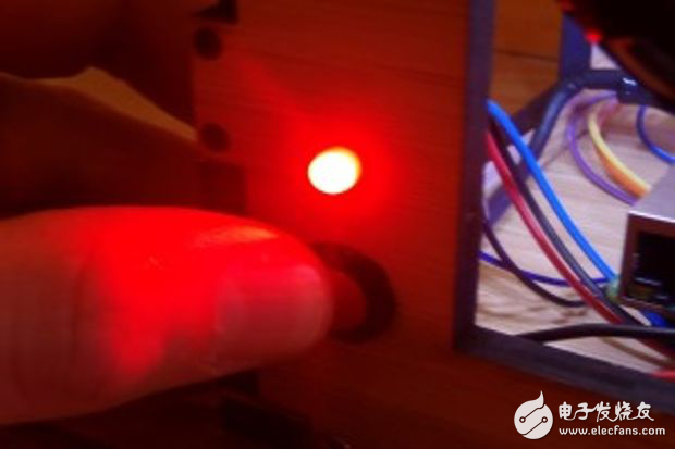
This script is a much easier to follow than to teach one, but it is equally important. Since the Raspberry Pi is also a full-featured computer, it should be properly shut down, but with different lethality, it can cause drive failure, data loss, and memory corruption.
To solve this problem, I installed a simple button for the RGB LED on the back of the box. The blue light can be switched continuously for more than one second, and the pie will be restarted when the button is released. Pressing the button for a few more seconds will cause the LED to turn red and the signal to turn off completely.
This feature is fully processed under the shutdown.py script. In the case of "forever loop" operation, the following will happen:
1.0.25 second sleep state
2. Check that a button is pressed (low state on the pin)
3. Repeat forever
1. Press the button and sleep for 1 second
2. Recheck the pin to see if the button is still pressed
3. If the button is still being held, we may have to restart it? If not, please feel free to check it out!
4. Set the RGB LED to blue
5. Sleep 2 seconds
6. Recheck the pins to see if the button is still pressed
7. If the button is still held, it should be turned off!
8. Set the RGB LED to red
9. If not, restart!
Step 9: Building the box
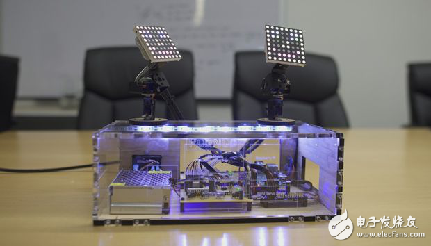
In the process of building this box, friend Eric creates a pair of vector files in Illustrator. These were sent to the laser cutting company (Ponoko), which sent us a laser cutting block and acrylic. These pieces were still very big when they were sent back, but people had the joy of assembling them.
If you are careful, you can drill the pilot holes in acrylic (and wood) and use thin screws to mount them together. If you don't want to do this, feel free to build the situation you want, from the parts list holder should be used to keep the circuit components firmly attached to the base, you can also reduce some extra holes, install the power supply on the back of the box Sockets, buttons and RGB leadership.
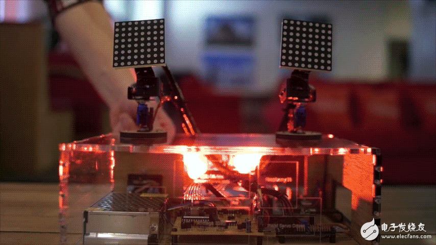
The most important thing is the installation of the servo rig. When they are on the move, the rudder opportunity causes any lightweight installation frame to fall or jump around. Crucially, they are firmly mounted on a sturdy surface, where the lid of the box is chosen!
Step 10: Finish
Some parts need to be customized, especially the actual box and servo bracket. As long as it is creative, do it boldly!
Toroidal Transformer,Toroidal Transformer Audio,Diy Toroidal Transformer,Toroidal Current Voltage Transformer
Guang Er Zhong(Zhaoqing)Electronics Co., Ltd , https://www.gezadapter.com