OverviewThis application note describes how to use the Keil µVision2 ™ suite of tools to build a C application for the Ultra-High-Speed ​​Flash family of microcontrollers, which includes the DS89C430, the DS89C440, and the DS89C450. The process of loading the compiled application into the microcontroller using Dallas / Maxim's Microcontroller Tool Kit application is also covered.
All development for this application note was done using the DS89C440 and the High-Speed ​​Microcontroller Evaluation Kit Board (Rev B). The C application was created and compiled using Keil's µVision2 version 2.40 and the Keil C51 Compiler version 7.10. The compiled application was loaded into the DS89C440 flash memory using the Microcontroller Tool Kit version 2.1.03.
Notes on the Ultra-High Speed ​​Flash Microcontroller FamilyThe microcontrollers in the Ultra-High Speed ​​Flash family are all programmed identically, with the same register set and memory mapping. The only difference between them is in the amount of internal flash memory they have, which is as follows.DS89C430 — 16 kB x 8 DS89C440 — 32 kB x 8 DS89C450 — 64 kB x 8 Creating and Compiling the C ApplicationThis section describes the process to create and compile a "Hello World" style application for the DS89C430 / 440/450 using Keil's µVision2 integrated development environment.
Creating a New Project
In Keil µVision2, select Project-> Create New Project from the menu. Enter the name of your new project.
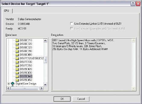
The Select Device for Target dialog will appear as shown below in Figure 1. Under Database, select Dallas Semiconductor and the particular microcontroller you are using (the DS89C430, DS89C440, or DS89C450). Hit OK to continue.

Figure 1. Selecting the device for a new Keil µVision2 project.
A new dialog box will ask, "Copy 8051 Startup Code to Project Folder and Add File to Project?" Select YES.
Setting Project Options
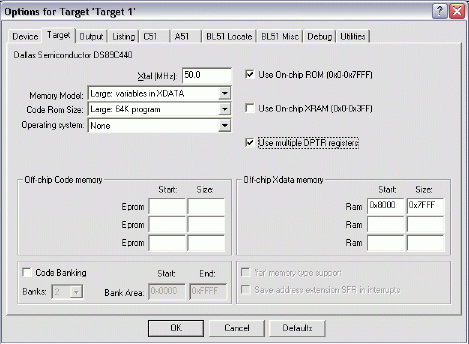
When the project window opens on the left, open up Target 1. Right click on Target 1, and select Options for Target 'Target 1'. An Option dialog box will appear. Select the Target tab. Change the settings in this tab as follows .

Figure 2. Target option settings for the DS89C430 / 440/450.
Next, select the Output tab. Set the checkbox for Create Hex File. This hex file will be required to load the project code into the microcontroller using the Microcontroller Tool Kit.
Adding the Project Code Open a new file and enter the following C code:
Save this file as main.c. The file will not be automatically added to the project. To add the file, right-click on Source Group 1 and select Add Files to Group 'Source Group 1'. Select main.c and click Add , then click Close.
Compiling and Loading the Project
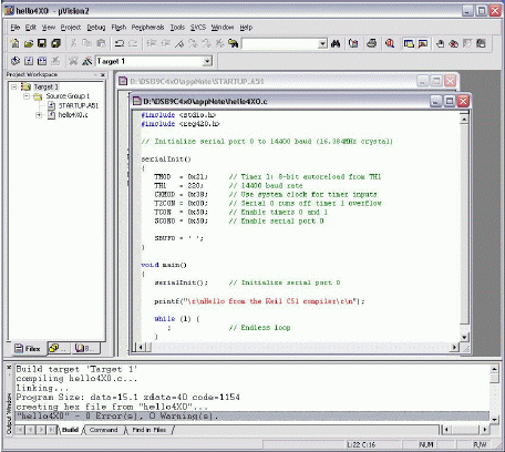
To compile the project, press F7, or select Project-> Build Target from the menu. If no errors occur, messages should appear indicating that compilation completed successfully, as shown in Figure 3.

Figure 3. Compilation output from Keil µVision.
The Microcontroller Tool Kit software is available from the Maxim / Dallas website at
Once the Microcontroller Tool Kit software is installed, open it. In the initial dialog box, select the device type you are using (DS89C430, DS89C440, or DS89C450). Next, select Options-> Configure Serial Port from the menu. Select the serial port that you are using to connect to the microcontroller system (such as COM1, COM2 ...) and select a baud rate of 14400 baud.
Power on the High-Speed ​​Microcontroller Evaluation Kit board at this point. The board should be set up as follows.
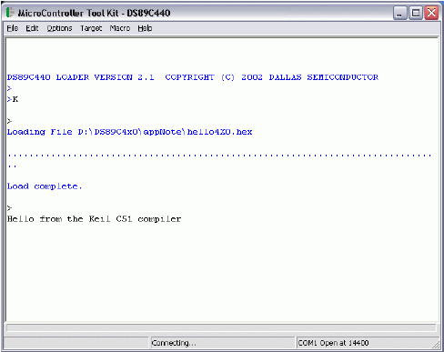
At the loader prompt, type 'K' and press enter. This erases the flash memory on the DS89C430 / 440/450. Next, select File-> Load Flash from the menu (or press Ctrl + O). Select the .hex file from your project's compiled output and click Open in the dialog box. A "Loading File ... Load complete message should appear."
At this point, simply turn off DIP switch SW4.1 to exit loader mode, and the application should execute and display the demonstration message over serial 0, which will be displayed in the Microcontroller Tool Kit window.

Figure 4. Loading and running the application in MTK.
Bare aluminium conductors are electrical conductors made from pure aluminium. They are used in various electrical applications, including overhead power transmission and distribution lines.
Bare aluminium conductors have several advantages over other types of conductors. Firstly, aluminium is lighter than copper, which makes it easier to handle and install. This is particularly important for overhead power lines, where the weight of the conductor can have a significant impact on the cost and feasibility of the project.
Secondly, aluminium has a higher conductivity-to-weight ratio than copper. This means that for a given weight, aluminium conductors can carry more current than copper conductors. This makes them more efficient in terms of power transmission.
However, bare aluminium conductors also have some disadvantages. One major drawback is their lower mechanical strength compared to copper conductors. This makes them more susceptible to sagging and stretching under the weight of their own span, especially in hot weather conditions. To address this issue, aluminium conductors are often reinforced with steel strands to improve their mechanical strength.
Another disadvantage is that aluminium has a higher resistance than copper, which can result in higher power losses and voltage drops. To mitigate this, aluminium conductors are typically designed with larger cross-sectional areas compared to copper conductors to compensate for the higher resistance.
Overall, bare aluminium conductors are widely used in electrical power transmission and distribution systems due to their cost-effectiveness, lightweight, and high conductivity-to-weight ratio. However, careful design and installation considerations are necessary to ensure their mechanical strength and minimize power losses.
Aluminium Bare Stranded Conductors,Bare Aluminium Conductors,Overhead Transmission Line, Transmission line Bare Aluminium Conductors
Ruitian Cable CO.,LTD. , https://www.rtpowercable.com
