design background:
A state machine is a timing behavior that describes various complex timings. It is one of the most important methods for designing mathematical logic using HDL. The state machine is divided into a mole machine and a rice machine. When the output is only related to the state, it is called a mole machine. When the output is not only related to the state but also related to the input signal, it is called a rice grinder, and the circuit prototype of the rice grinder and the Molar machine I will not introduce here.
The state machine is composed of a status register and a combinational logic circuit, and can perform state transition according to a pre-designed state according to a control signal, and is a control center that coordinates the action of related signals and completes a specific operation. For example, the problems encountered in our lives, health --- cold --- health, this is a state transition map, from health to cold state to health.
Â
Design principle : Â
I think for us beginners, as long as the state machine is this state, that is, when this clock comes, this happens. When the clock comes, something else happens, that is, after this happens. Another thing happens to jump to the next clock, and it doesn't matter if two things happen. We understand that beginners understand this, and do not need to understand the profound two-stage, three-stage.
We will use a simple state machine in the design below to make everyone understand a simple state machine.
Our design is also a water lamp. Our design is to make all 4 extinguishments on reset , the first rising edge light up, the second light up the next, and so on.
We can think of this way, when the first state is a rising edge to light the first lamp, then jump to the next state to light the second lamp, and the third to light the next. . . .
Â
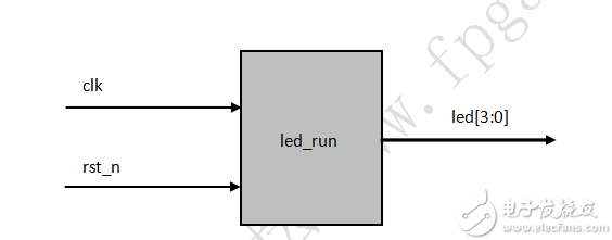
Design architecture diagram :

Â
Design code :
Design module
0 Â Module led_run ( clk , rst_n , led );
1 Â
2 Â Input clk , rst_n ; // Define the input and output
3 Â
4  Output  Reg  [ 3 : 0 ] led ;  Â
5 Â
6  Reg  [ 10 : 0 ] count ;  // define a time register
7 Â Reg clk_1hz ; // define a clock
8  Reg  [ 1 : 0 ] state ;     // Define the status
9 Â
10 always  @  ( posedge clk )    Â
11 if (! rst_n )
12 begin
13 clk_1hz <= Â 1 ;
14 count <= Â 0 ;
15 end
16 else  If ( count <  ( 5  /  1  /  2   -  1 ))   // Count to generate a clock
17 count <= count + Â 1'd1 ;
18 else
19 begin
20 count <= Â 26'd0 ;
21 clk_1hz <= Â ~ clk_1hz ;
22 end
twenty three
24 always  @  ( posedge clk_1hz )
25 if (! rst_n )
26 led <= Â 4'b1111 ; Â Â // reset off 4 lights
27 else
28 case  ( state )
29 0 : begin // The first state lights up the first light, then jumps to the next state
30 state <= Â 1 ; Â Â Â
31 led <= Â 4'b1110 ;
32 end
33
34 1 : begin // The second state lights up the second lamp, then jumps to the next state
35 state <= Â 2 ;
36 led <= Â 4'b1101 ;
37 end
38
39 2 : begin // The 3rd state lights up the 3rd lamp, then jumps to the next state
40 state <= Â 3 ;
41 led <= Â 4'b1011 ;
42 end
43 3 : begin // The 4th state lights up the 4th lamp, and then jumps to 0 state.
44 state <= Â 0 ;
45 led <= Â 4'b0111 ;
46 end
47
48 default  : state <=  0 ;  // Otherwise jump 0 state
49 endcase
50
51 Â Endmodule Â
Â
Test module
0  `timescale  1ns / 1ps   // instantiation time stamp
1 Â
2 Â Module tb ();
3 Â
4 Â Reg clk , rst_n ;
5  Wire  [ 3 : 0 ] led ;  Â
6 Â
7  Initial  Begin
8 Â
9 Â Clk = Â 1 ;
10 rst_n = Â 0 ;
11
12 # 200.1 rst_n = Â 1 ;
13
14
Butt Connector,Lugs Insulated Female Connectors,Insulated Female Connectors,Non-Insulated Spade Terminals Wire Connector
Taixing Longyi Terminals Co.,Ltd. , https://www.longyiterminals.com
