In the field of mobile devices and consumer applications, low power consumption is undoubtedly the most mainstream design thinking. However, for system products in many other application areas, low power consumption is also the focus of product design. For example, for instruments installed in remote areas in inaccessible areas, or sensing systems installed in places that are inaccessible to humans, such as underground and seabed, the lower the power consumption, the financial cost and difficulty of maintenance can be greatly reduced.
In such applications, the system must not only have low power consumption, but also must be extremely robust, because such products may operate in environments with drastic temperature changes, high humidity, high pressure, or the presence of pollutants, and the environmental conditions are extremely strict. Harsh.
In various sensing applications, position sensing is a very common application requirement, but the previous position sensing methods are either sturdy or doubtful or have relatively high power consumption. However, as technology advances, it is no longer a problem to achieve position sensing with both high robustness and low power consumption characteristics.
Position sensing applications ubiquitous potential/optical coding has a lack of robustness
Whether in the simplest or most complex applications, rotary and linear position sensing are common requirements.
Generally speaking, if it is to develop a relatively simple application, designers usually tend to use a typical potentiometer (Potentiometer) as a position sensor, and more demanding applications usually use an optical encoder. However, if robustness and tolerance to harsh conditions are added to the list of requirements, these devices are not the most ideal choice. Potentiometers are prone to various electrical and mechanical failures, causing component failures. In addition, whether it is an optical encoder or a potentiometer, its operation is easily affected by contaminants such as dust, dirt, grease, and liquid; severe impact or vibration will also make these devices unable to maintain accurate measurement output.
The sensor is sealed to avoid contamination by environmental substances. However, this method is expensive and may sacrifice the assembly or mechanism design of the host product, and any damage or aging of the sealing body may shorten the operating life of the sensor system.
Magnetic position sensing is robust and the power consumption problem has been greatly improved
In addition to optical encoders, there is another way to achieve non-contact sensing, that is, magnetic position sensing. However, in the past, most applications with stricter power consumption requirements did not like the use of magnetic position sensors, because such components gave people the stereotype of high power consumption. From the operating mode of the magnetic position sensor, such a stereotype is not wrong, but with the advancement of technology, such a view is now outdated.
Nevertheless, the principle of magnetic sensing is worth studying in order to understand why power issues are the cause of designers' doubts. The Hall Effect, discovered by Edwin Hall, explains how a magnetic field affects the current flowing through a conductor. Simply put, the working principle of the Hall-effect electromagnetic sensor is that the magnetic field (B) acting perpendicular to a conductor will affect the current (I) flowing through the conductor (Figure 1). The rotation of a two-pole magnet will make nearby conductors feel the magnetic field strength changes as the polarity swings from the N pole to the S pole and back again. This change in the magnetic field will proportionally affect the current flowing through the conductor. This continuously changing current will form the conductor's voltage (VH), which is easy to measure.
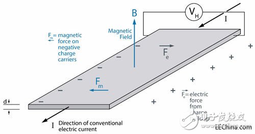
Figure 1 The Hall effect explains how a magnetic field affects the current flowing through a conductor
In the magnetic position sensor (MPOS), the voltage signal can be converted into angle or linear displacement measurement results through mathematical operations. But in order for the sensor to work, it is necessary to have current flowing through the conductor to activate the Hall element.
Because Hall sensors draw current in this way, they generally use more current than other technologies, such as potentiometers and optical encoders. Today's Hall sensing uses silicon components to generate voltage, and integrates signal processing and calculation functions into a single circuit. However, this current, which is affected by the magnetic field, is still the core of the entire component's operation.
MPOS has an advantage over potentiometers and helps to alleviate power consumption problems. The potentiometer is a passive electromechanical device that cannot allow the design engineer to configure its power setting. The potentiometer is always on and always draws the same current. And MPOS is an intelligent device with built-in control and configuration circuit, which can realize various low power consumption settings.
The most significant power-saving method of MPOS is power cycle. In the Stop mode, the power consumption can be reduced to zero. However, MPOS does require more current during startup than during stable operation, and it also requires processing time during startup. As a result, there is a delay between the time when a certain action starts and the time when MPOS provides displacement measurement, which becomes a problem. This is unacceptable in some applications.
There is another way to reduce the power consumption of the MPOS, that is, to power off the unimportant components in the sensor and only provide power to them when they need to be measured. The more circuit components are de-energized, the longer it takes for the sensor to start sampling after it is de-energized.
To help designers achieve the right balance between speed and power in any particular application, austriamicrosystems has recently released a series of rotary MPOS, which can provide users with deep and shallow power-off modes. The two low-power states and the "Always On" mode each support different sampling rates. This allows designers to choose a sampling rate that suits the overall system power requirements.
In deep power-down mode, the sensor only draws 3μA current, and the maximum power consumption is 9.9μW. Another low-power mode will keep the power-on reset circuit active; in this mode, the chip will draw 33μA of current, and the maximum power consumption is 108.9μW. In "normal" mode, the maximum power consumption is 28mW. The nominal time required to start the device is 580μs, and the delay between sample capture and interrupt output to the microcontroller is 500μs.
Case study of underwater motor drive
Having said so much about the theory and operation of MPOS, how reliable is their actual operation in harsh environments?
In order to answer this question, I designed a simple underwater motor drive application using austriamicrosystems' AS5055A standard MPOS. This component produces a digital output, which, although not immediately visible on the oscilloscope, can be displayed in the graphical user interface (GUI).
AS5055A is installed on a standard adapter board, and its power supply and output pins are connected with wires. The entire circuit board is coated with off-the-shelf rubber paint commonly found in DIY shops (Figure 2).
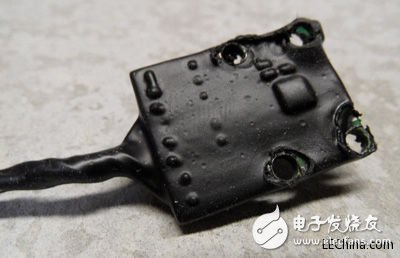
Figure 2 AS5055A position sensor adapter board after protective coating.
After the preparation is complete, connect a simple direct current (DC) motor to this fixture, and a 6mm diameter magnet connected to the bottom of the motor should be located directly above the AS5055A chip on the adapter board (Figure 3).
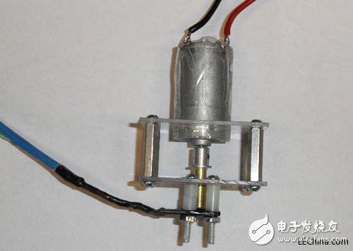
Figure 3 The magnet installed on the motor is located directly above the AS5055A magnetic position sensor.
After the assembly is complete, install the backing board and immerse it in 2.5 cm deep water (Figure 4). Send the power to the motor and the adapter board circuit, and you can see the sensing output from the AS5055A in the GUI in Figure 5: Since the interface connected to the AS5055A is digital, only real-time screenshots will be displayed. MPOS works as expected, and the GUI displays the captured angular displacement measurement value.
Figure 4 AS5055A adapter plate is completely immersed in water.
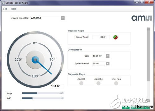
Figure 5 Output value from AS5055A immersed in water
Using the same coating and immersion method, a similar test output is also displayed on the display screen of the oscilloscope (Figure 6). This triangular waveform shows that the magnet continues to rotate 360°. At 0°, the analog output voltage from MPOS is the minimum; at 360°, it is the maximum. These two tests show that the solution works reliably.
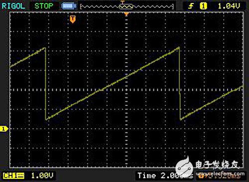
Figure 6 shows the output signal of AS5055A on the oscilloscope
This protective coating can provide the effect of hardening MPOS, enabling it to operate in harsh environments. Interestingly, its effect is like the pollution effect of some foreign objects, such as dust, grease or dirt. Such hardening treatment will completely invalidate the potentiometer or optical encoder, but the function of MPOS will not be affected at all.
Low-power MPOS opens up new areas of application
How to use this new generation of low-power MPOS? The contact points of the potentiometer and the optical system of the optical encoder can easily affect the normal operation of the function due to damage or dirt on the surface, and the magnetic solution will not be affected by these factors. The function of MPOS is to sense the rotational movement of the magnet, and the magnet and the sensor are separated by a gap of 1.5~3mm. There are no contact points or moving parts, so there will be no mechanical wear, and no dust, grease or liquid will enter. Rotating mechanism and soiling of the optical code wheel (OpTIcal Code Wheel) occurred. On the whole, in a more polluted environment, replacing potentiometers or optical encoders with MPOS is a more reliable choice.
Another benefit of the non-contact sensing method is Intrinsic Safety. Intrinsic safety is a protective technology that limits the energy that can be used for ignition to ensure the safe operation of electronic equipment in hazardous areas. Due to the frictionless design, the non-contact solution does not originally generate sparks, and can easily implement circuits that meet the requirements of intrinsic safety.
For electronic equipment manufacturers in the field of underwater oil exploration and extraction, low-power operation is also of great benefit. In deepwater oil and gas facilities, remote control and intrinsically safe sensors are necessary. In such applications, low power consumption and magnetic position sensing technology that is not affected by high pressure and immersed in petroleum environments has significant advantages.
In remote or battery-powered equipment, and in systems such as intrinsically safe circuits, low-power operation is a basic requirement. If it is also necessary to not be affected by pressure, liquid, dust or dirt, similar position sensors, such as Potentiometers and optical encoders are not applicable without complicated and expensive shielding and protection.
Therefore, the ability to provide a new generation of magnetic position sensors that can optionally support low-power modes will allow engineers to develop accurate and stable position sensing systems while meeting extremely low-power system requirements.
A27 3000 Puffs,Replaceable Atomizer Vape Atomizer,A27 3000 Puffs Healthy,A27 3000 Puffs Made
Lensen Electronics Co., Ltd , https://www.lensenvape.com
