The KJ006/ KJ005 thyristor phase shifting circuit is mainly suitable for AC phase control of bidirectional thyristor or anti-parallel thyristor lines directly powered by AC. It can be directly powered by the AC grid without the need for external synchronization signals, output pulse transformers and external DC power supplies, and can be directly coupled to the thyristor control pole. It has the advantages of good sawtooth wave linearity, wide phase shift range, simple control mode, mismatch protection, large output current, etc. It is an ideal circuit for AC dimming and voltage regulation. The KJ006/ KJ005 thyristor phase shifting circuit is also suitable for phase control of half-controlled or fully-controlled bridged lines, as well as DC power supply.
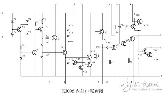
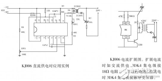
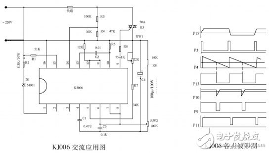
Circuit working principle: KJ006/ KJ005 SCR phase shifting circuit is composed of synchronous detection, sawtooth wave forming circuit, phase shift voltage and sawtooth voltage integrated comparison and amplification circuit, power amplifier circuit and loss-of-interference protection circuit. KJ006/ KJ005 thyristor phase shift circuit circuit schematic and application examples are shown below. The sawtooth wave slope is determined by the values ​​of R7, RW1, and C1. The slope of the sawtooth wave is adjusted by the 5-pin external potentiometer RW1. The sawtooth wave is compared with the phase shift control voltage introduced by the 6-pin, and is differentiated by the external R5 and C2. The pulse width is determined by the values ​​of R5 and C2, and then output by the 9-pin power amplification, which can obtain an output load capacity of 200 mA. When the monostable differential trigger pulse from the comparison amplifier does not trigger the thyristor, the detection signal obtained from the 14-pin is connected through the 11-pin and 12-pin, so that the 9-pin outputs a pulse to the thyristor, so that the inductive load is Very advantageous, in addition, can also play the role of sawtooth wave and phase shift control voltage drop protection. If it is purely for the protection of the mismatch, the mismatch pulse can also be output from the 2nd leg, and the 2nd leg and the 12th pin can also be connected to each other. Application examples and extended current application diagrams when using DC power supply are shown on the next page. For different grid voltages, the KJ006 circuit synchronous current limiting resistor R1 is selected as follows, R1 = grid voltage / 3 ~ 4 & TImes; X100Ω

Package form:
KJ006/ KJ005 thyristor phase shifting circuit adopts double-row in-line C-16 white porcelain and black porcelain two-package package, and the external dimensions are in accordance with the standard “Semiconductor Integrated Circuit Dimensions†SIll00-76 issued by the Ministry of Electronics Industry.
Typical wiring diagram and waveforms at each point


Electrical parameters:
Power supply voltage: self-generated DC power supply voltage +12V ~ 14V; external DC power supply voltage +15V, allowed to fluctuate ± 5% (±10% function is normal). Supply current: ≤12mA. Synchronous voltage: ≥10V (effective value). Synchronous input allows maximum synchronous current: 6mA (rms) phase shift range ≥1700 (synchronous voltage 220V, synchronous input resistance 5lkΩ). The phase shift input terminal bias current is ≤10μA.
Output pulse:
(1) Width: 100μS - 2mS (achieved by changing the pulse width RC element). (2) Amplitude: ≥13V (when the power supply voltage is 15V). (3) Maximum output capability: 200 mA (absorption pulse current). (4) Output tube pressure: BVCEO ≥ 18V (test condition Ie ≤ 100 μA).
Sawtooth amplitude: 7 ~ 8.5V. The maximum input current of the thyristor detection terminal: 6mA (effective value), positive and negative half cycle pulse phase imbalance: ≤ soil 30. KJ005 is a special case of KJ006. There is no self-generated power supply and it cannot be used directly in AC power supply. There is no out of the detection input (14 feet empty) and the output M (11 feet empty) with 2 feet and 12 feet connected to play the role of mismatch protection. The KJ005 is powered by DC power and is identical to the KJ006.
Description:
The 847-Pro Mining Motherboard is a basic motherboard that supports 20 graphics cards, the boards used for Ethereum and other less resource-intensive scripts. The cards connect via PCIe-over-USB and each port has is individually controlled and managed by on-board diagnostics.
Support 1660, 2070, 3090, rx580 and other full series of graphics cards.
Support common mining cards, such as: RX series, GTX10 series, gtx20 series, gtx30 series, etc.
This motherboard has a large display card pitch of 65mm, which is more stable without switching.
The
motherboard adopts HM65 chip, all solid capacitors, gigabit network
card, integrated notebook CPU, DDR3 notebook memory slot.
motherboard,mainboard,asus-motherboard,motherboard price
Easy Electronic Technology Co.,Ltd , https://www.pcelectronicgroup.com
