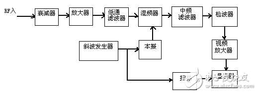
In the measurement of some CATV system indicators, the spectrum analyzer is often used. In order to make the measurement result accurate, the problem of the resolution bandwidth setting is often involved in the use of the spectrum analyzer. To understand this problem, you need to know the basic principles of some spectrum analyzers. Figure 1 is a basic block diagram of the spectrum analyzer. The IF frequency in the figure (the input signal is generated by the sum or difference frequency of the local oscillator signal), the local oscillator is controlled by the ramp generator. Under the control of the ramp generator, the local oscillator frequency will be low to high. Linear change. Thus, when displayed, the ramp voltage generated by the ramp generator is applied to the X-axis of the display, and the detector output is connected to the Y-axis via a low-pass filter, and the ramp generator is scanned on the display when the local oscillator frequency is scanned. The spectrum of the input signal is automatically plotted. The low-pass filter at the output of the detector is called a video filter and is used to smooth the response during the analysis scan.

Figure 1 Block diagram of the spectrum analyzer
1, resolution bandwidth
In spectrum analyzers, frequency resolution is a very important concept, which is determined by the bandwidth of the IF filter, which determines the resolution bandwidth of the instrument. For example, the bandwidth of the filter is 100KHZ. Then the spectral line frequency has an uncertainty of 100KHZ, that is, within the bandwidth frequency range of one filter, if two spectral lines appear, the instrument cannot detect the two spectral lines, but only one spectral line is displayed. The line level (power) reflected by the instrument is a superposition of the level power of the two lines. Therefore, measurement errors will occur. Therefore, for two closely related lines, the resolution depends on the bandwidth of the filter.

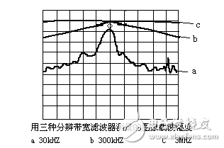
figure 2
Taking the measured carrier level as an example, we compare the resolution bandwidth settings of the instrument. Figure 2 shows the spectral curves of the resolution bandwidth (from bottom to top) of 30KHZ, 300KHZ, and 3MHZ (input as a single carrier signal). When bandwidth is used, we consider whether the instrument has enough bandwidth to fully respond to the input signal. The correct method is to broaden the bandwidth of the filter. When the signal carrier amplitude is no longer increased on the screen, it means the IF filter pair. The response of the input signal has sufficient bandwidth. In the figure, we can see that when the resolution bandwidth changes from 300KHZ to 3MHZ, the displayed signal amplitude does not change, which makes it considered that 300KHZ bandwidth is sufficient. In addition, when the resolution bandwidth is set between 300KHZ and 3MHZ, there is no change in the signal amplitude for a single carrier, but the actual resolution of the image carrier level of the CATV system cannot set the resolution bandwidth to 3 MHz, because in practice There is a sound carrier of adjacent channels near the image carrier (1.5MHZ apart), and the 3MHZ bandwidth cannot filter the energy of the adjacent sound carrier, so that the energy of the adjacent sound carrier is added to the image carrier being measured, so that The measured level value is higher than the actual value.

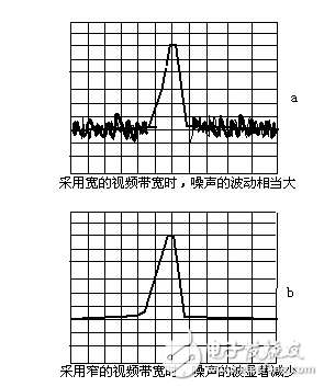
image 3
2, video filter
The filter behind the detector in Figure 1 is called a detector filter, also called a video filter. It is a low-pass filter that acts to reduce the noise variation at the detector output, revealing that some have been masked and close to the present. The noise floor signal, if it is measuring noise power, also helps to stabilize the measurement.
The output of the detector often has a DC component and an AC component. The DC component represents the energy present in the IF bandwidth. Therefore, the DC component can be extracted by the video filter to remove some AC components, which can give a more stable noise-free output. Figure 3 is a signal diagram of the detector output under different video bandwidths. Figure 3a uses a wideband video filter, and Figure 3b uses a narrowband video filter. As can be seen from the figure, the noise fluctuation is large when using a wideband filter. The ripple is significantly reduced in the narrow-band filter, and the noise average is the same, that is, the filter does not lower the average noise level, but it can reduce the peak level of the noise. This exposes a low level signal that cannot be seen with a wider video filter. But in some cases, such as the analysis of some special noise signals, we need a wider video filter bandwidth for observation and analysis, so we can set the bandwidth of the video filter according to different situations.
The relationship between the bandwidth of the video filter and the resolution bandwidth is that the noise before detection can be reduced by a narrower resolution bandwidth, thereby reducing the noise output level of the detector; the detected noise is smoothed by a narrowband video filter to reduce noise. Fluctuating, but not reducing the average power level of the noise.
Dc 12V Controller,Automatic Switch Charge Controller,New Solar Charging Controller,Rohs Charge Controller
GuangZhou HanFong New Energy Technology Co. , Ltd. , https://www.zjgzinverter.com
