Battery-powered devices usually have a power indicator. But this indicator light may consume a lot of power. A low duty cycle flash can be used to provide an appropriate indication of the power-on state, in which case the simple circuit described herein can be used.
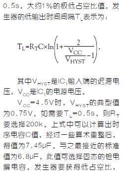
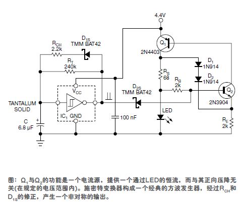
The SN74AHC1G14 is a miniature single Schmitt trigger logic inverter, plus two resistors, a Schottky diode and a capacitor, which form the timing generator for the flash, as shown. The period of the output waveform is approximately

It is necessary to speed up the charging time of capacitor C to shorten the high output time TL. The implementation method is to increase the resistance RCH and the forward voltage drop of the series Schottky diode D1S.D1S to not exceed 200mV, which can be ignored. The lighting time of the LED is approximately (1/100) × TL ≈ 5ms.

The LED driver includes a PNP bipolar transistor Q1 and an NPN bipolar transistor Q2. Q1 and Q2 form a switchable current source. When the cathode of the Schottky diode D2S has a high logic level, the LED passes through a constant current, and the current value is about IO≈0.7V/RS, which is 10mA in this circuit.
The series connected silicon diodes D1 and D2 provide powerful nonlinear negative feedback. If, for any reason, the voltage drop across the sense resistor RS rises, the connection of D1 to D2 forces the Q2 emitter voltage to produce nearly the same boost. This boost reduces the Q2 collector current and therefore also reduces the Q1 base current, creating a closed loop. The final result is to reduce the Q1 collector current to a constant value.
Note that when the output of IC1 is low, the current through D2S and resistor RB can be ignored. This is because when the IC1 output is low, the base of Q2 remains low, causing it to turn off both with the current source. When the current source is turned off, the LED is also extinguished. At this time, only the micro-ampere leakage current passes through the D2S and RB. If the surface mount component is used, the circuit can be fabricated on a board of no more than 16 mm × 16 mm.
This work was supported by the Slovak Research and Development Agency under contract number APVV-0062-11s.
Digital display meter is the abbreviation of digital display instrument. LED and LCD are commonly used as display elements.
Digital display meter has the characteristics of visual intuition, convenient setting and high degree of intelligent control. In addition, with the rapid development of current sensing technology, the function of digital display instrument is becoming more and more powerful and the accuracy is constantly improving. Digital display instrument is replacing traditional mechanical instrument in a large number and has been widely used in all walks of life and daily life.
Digital Display Meter,Digital Display Intelligent Meter,Electrical Connection Digital Display Meter,Intelligent Digital Panel Instrument
Taizhou Jiabo Instrument Technology Co., Ltd. , https://www.jbcbyq.com
