
The main task of the hardware design flow is to define a circuit board. Basic components such as memory types, bus protocols, and I/O have been predefined.
If only a fixed processor is used, it is also predefined. However, a single processor cannot run algorithms that require gigabit performance (such as packet processing algorithms), and multiple processors need to work together.
The best way to build a processing building block depends on the software you are running. Using FPGAs for processing allows you to make a clear decision about the exact implementation after you have a better understanding of the code requirements. The new Tejia FP platform provides a method and multi-core infrastructure on the Xilinx VirtexTM-4 FPGA, enabling developers to fine-tune multi-core architectures after code is written.
When software engineers design hardware
Hardware and software design are two fundamentally different tasks. No matter how much a hardware design language is like a piece of software, it is still hardware design. The hardware language defines the structure, and the design process ultimately requires structural materialization. However, software engineers are increasingly using C programming techniques to design system functions; existing tools support the use of software or hardware methods to design system functions.
Software-implemented methods are more process-oriented. It considers the question of "how to do it" instead of "building what," because from a traditional point of view, there is no need to build anything - the hardware is already built. In a truly software-based design approach, the key functions are not built into a structure, but are instead structured to be implemented in an already-built system. Flexibility is based on the advantages of a software implementation method: it can still be changed quickly and easily after the system leaves the factory. Although FPGAs can also be programmed in the field, changing the software design is much faster than building hardware.
Due to differences in hardware and software design, the hardware and software designers have different concerns. It is impossible for a hardware engineer to become a software engineer by simply changing the syntax of a programming language. Conversely, software engineers can't possibly turn into hardware engineers because of the software's involvement in hardware design. Therefore, software engineers cannot be added lightly to the design of the processing architecture.
In addition, hardware engineers, software engineers, or project managers will not agree to give a hardware engineer a design to a software engineer. The method used by software engineers to make decisions about hardware is likely to be recognized by another software engineer who is familiar with similar programming languages.
As shown in Figure 1, the parallel pipeline is the key structure of the processing architecture in the multi-core packet processing engine. This engine consists of a processor array plus possible hardware accelerators. Answering the following questions is equivalent to completing a design process:
How many processors are needed?
How should these processors be arranged?
How much code does each processor need to process and how much local data is stored?
Which parts of the code need hardware acceleration
Let us answer these questions one by one, so as to "assemble" a set of design methods for software engineers.
The number and configuration of processors
The number of processors required can be calculated by simple mathematical calculations of the cycle budget and the number of cycles required to execute the code. When you have to complete the work within the specified time, the cycle budget becomes a key parameter. For example, when performing grouping processing, data locations are divided. In this way, it is possible to design the hardware around the division without using hardware. How software engineers design is a key issue. Teja integrates a set of APIs and a processing tool that can use ANSI C to define the hardware platform. This tool executes the program and creates a definition of the processing platform that can be processed by the Xilinx embedded tool. The API group is very rich in content and can be controlled at the very bottom of the hardware level, but most software engineers do not want to use them. Therefore, Teja also added a "typical" pipeline definition method in a parametric way. To implement the pipeline in the above example, simply modify the two simple #define statements in the configuration header file.
The following statement defines a two-stage pipeline using four engines in the first stage and two engines in the second stage: Figure 1 - Parallel pipelines, each with a MICroBlaze processor, dedicated memory It is constructed with an optional lighter. The package comes in and you only have so many cycles to complete your work before the next packet arrives. If your code takes longer to execute, then you need to add more processors. For example, if the cycle budget is 100 cycles and the code execution requires 520 cycles, then you need 6 processors (520 divided by 100 and then rounded to an integer). You can adjust the number of processors, but must meet the budget requirements. When using the Teja tool, the number of cycles can be determined by analysis.
The next question is how to arrange these processors. The easiest way to deal with this problem is to determine if you need to divide the code to create a pipeline. The pipeline uses less hardware resources but increases latency. If you need to divide the code, it's best to choose one obvious location (natural and intuitive). It is not necessary to calculate the precise position of the midpoint of the cycle.
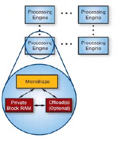
Figure 1 - Parallel pipeline, each engine consists of a MICroBlaze processor, dedicated memory, and optional subtractor
Suppose you want to use a six-processor pipeline to form a two-stage pipeline. Then you need to calculate the number of processors required at each stage. First, determine the number of cycles for each partition by analyzing it. If you then use it to remove the periodic budget, you can get the required processing for each level. The number of devices. . Therefore, if the first partition requires 380 cycles, it requires 4 processors; thus the second level requires 140 cycles, thus requiring two processors. (The sum of the number of cycles required for the two divisions does not actually equal the number of cycles required for the undivided procedure, but it will be very close, so it can be approximated as equal.) Therefore, the two-stage pipeline The first level requires 4 processors and the second level requires 2 processors. With sufficient logic resources, any such pipeline can be instantiated using the Xilinx MicroBlazeTM soft core.
In comparison, in a fixed pipeline architecture, the number of processors in each stage has been predetermined. Therefore, it can only be forced to use a special division method, and it will take a long time to realize this division. Conversely, if the number of processors used at each stage is different, the pipeline can be customized and can be irregular. So it can be divided from any location. In this way, it is possible to design the hardware around the division without using hardware.
How software engineers design is a key issue. Teja integrates a set of APIs and a processing tool that can use ANSI C to define the hardware platform. This tool executes the program and creates a definition of the processing platform that can be processed by the Xilinx embedded tool. The API group is very rich in content and can be controlled at the very bottom of the hardware level, but most software engineers do not want to use them. Therefore, Teja also added a "typical" pipeline definition method in a parametric way. To implement the pipeline in the above example, simply modify the two simple #define statements in the configuration header file.
The following statement defines a two-stage pipeline with four engines at the first level and two engines at the second level:
#define PIPELINE_LENGTH 2
#define PIPELINE_CONFIG {4,2};
From the above statement and the preset configuration program, the TejaCC program can build a pipeline. Of course, if the configuration of the pipeline needs to be changed for any reason, it is only necessary to use a method similar to the above to edit.
Memory
The third problem is related to the amount of memory required. In a typical system, the amount of code and data that can be stored is fixed. If your design does not meet this requirement, you need to do a lot of work to compress the extra content into storage space. However, when using an FPGA, as long as the required number of memories is within the range that the chip can provide, it can allocate storage space for each processor according to actual needs. In a more typical case, all memory spaces are the same size (because the minimum size of each block is 2k, which limits the degree of fine-tuning).
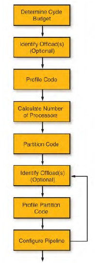
Figure 2 - Process for Configuring a Parallel Pipeline
The code compiles to provide the required memory size, and you can use the following statement to edit the configuration header file. In this example, the memory allocated for the code and data storage is 8 KB:
#define CPE_CODE_MEM_SIZE_KB 8
#define CPE_DATA_MEM_SIZE_KB 8
Use a subtracter to speed up processing
The fourth problem is related to creating hardware accelerators. There may be a part of the program that takes up too many cycles. To reduce cycles requires more processors, and using hardware accelerators can reduce the number of processors. As long as the hardware accelerator takes up less gates than the processor it replaces, the entire hardware implementation area can be reduced.
One of Teja's functions is to create such accelerators or subtractors directly from the code. By annotating the program, this function can be created:
Hardware Logic for Implementing Code Adding an Accelerator to the Processor Infrastructure via the System Interface Calling the Initial Code in the Prototype Replacement Program Before using the subtracter in the system, verify it with a test bench.
Once you have created a subtracter, the number of cycles will decrease, so you need to rearrange the processor. However, this is a very simple task because it is very convenient to redefine the structure of the pipeline.
A simple and straightforward method
Combining the previously described steps together results in the design flow shown in FIG. You can define the subtracter first (for tasks that obviously require a subtracter) or define the subtracter after the pipeline is configured (if the existing code uses too many processors).
What software engineers can control are some parameters that are natural and simple to them, and they are expressed using natural software language (ANSI C). All the details of materializing the hardware are handled by the TejaCC program, which creates a project for the Xilinx Embedded Development System (EDK). The rest of the work of compiling/synthesis/layout/wiring and generating bitstreams and mirroring code is all done by the EDK.
In this way, the board can be designed by the hardware engineer, but by using the FPGA, the hardware engineer can leave the key part of the hardware configuration in the final implementation to the software designer. This method also supports changes to the board as the design is about to be completed (for example, changes to the memory type and capacity due to performance reasons). Because Teja tools can create hardware definitions for FPGAs, including memory controllers and other peripherals, designers can easily adjust the board. The end result is that because hardware implementations can adapt to software changes, software designers no longer need to spend a lot of time writing programs around a fixed hardware setup.
By using the flexible Virtex-4 FPGA and MICroBlaze core, the Teja FP environment and basic architecture make all of this possible. With this powerful tool, you can shorten the development cycle by weeks or even months.
Teja also provides advanced applications that can be used to start a project and reduce the amount of work required. By combining a flexible and time-saving design approach with a pre-defined application, network equipment manufacturers can complete their designs faster.
Tinned Copper Braided Sleeve,Copper Pipe Insulation Tape,Thermobreak Pipe Insulation,Copper Pipe Covering
Shenzhen Huiyunhai Tech.Co., Ltd. , https://www.cablesleevefactory.com