Description:
The document does not list all the methods for WINCC to connect to Siemens brand PLC, but only lists some commonly used methods.
The parameter settings in various connection methods may be slightly different. The steps and parameters listed here are just a set of setting methods that can be connected.
One. WINCC uses CP5611 communication card to connect PLC through MPI
Prerequisites
I) The prerequisite for the communication between the PLC system and WINCC6.0 through CP5611 is to install the CP5611 communication board on the computer with WINCC.
II) Use STEP7 programming software to be able to connect PLC normally through MPI.
1. STEP 7 hardware configuration
STEP7 sets up MPI communication, the specific steps are not detailed here, please refer to the following figure 1.1:
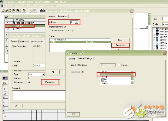
Figure 1.1
note:
1. Create a new MPI network for communication, set the address and baud rate of the MPI network, and remember that it needs to be matched in the subsequent settings.
2. Install CP5611 communication board
Install CP5611 and install the driver. For the specific installation process and precautions of CP5611, please refer to the following link:
http://support.automation.siemens.com/WW/view/en/26707026
3. Add driver and system parameter settings
Open the WINCC project in Tag Management--"SIMATIC S7 PROTOCOL SUITE-"MPI
Right-click MPI, click System Parameter in the pop-up menu, the System Parameter-MPI dialog box will pop up, select the Unit tab, and view the Logic device name. After the default installation, the logical device name is MPI
As shown in Figure 1.3:
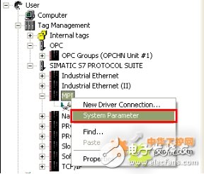
Figure 1.2
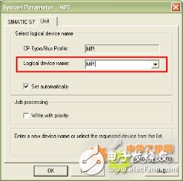
Figure 1.3
4. Set PG/PC Interface
Enter the control panel under the operating system and double-click the Set PG/PC Interface icon. In the Access Point of the ApplicaTIon: drop-down list, select MPI (WINCC), as shown in Figure 1.4, and then in the Interface Parameter Assignment Used: list, click CP5611 (MPI), and then in the Access Point of the ApplicaTIon: drop-down The list shows: MPI (WINCC) Ã CP5611 (MPI), as shown in Figure 1.5:
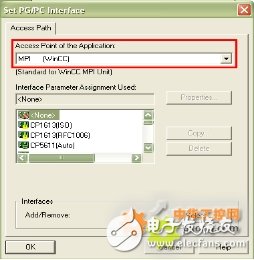
Figure 1.4
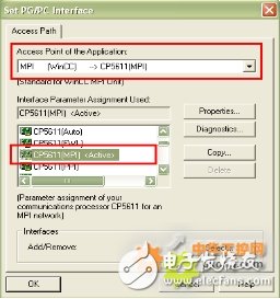
Figure 1.5
Set the communication parameters of CP5611, click ProerTIes... Button, the Properties-CP5611 (MPI) dialog box pops up, set the parameters, as shown in Figure 1.6:
The important parameters are as follows:
Address:
CP5611 address (MPI address must be unique, it is recommended to set it to 0)
Transmission Rate:
The transmission rate of the MPI network (the default is 187.5Kbps), you can modify it, but it must be the same as the transmission rate of the MPI port actually connected to the PLC)
Highest Station Address:
The highest station address of the MPI network (must be the same as the MPI network parameter setting of the PLC)
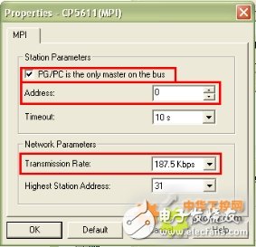
Figure 1.6
To diagnose the MPI network, click the Diagnostic... button to enter the diagnostic dialog box. As shown in the figure below: After the Test button is clicked, OK is displayed, indicating that the CP5611 is working normally. After clicking the "Read" button, the station addresses of all devices connected to the MPI network will be displayed. If you can only read your own station address, please check the MPI network and hardware connection settings at this time, and only those that have successfully read the CPU Only the site address can proceed with the following steps, otherwise, it will be impossible to establish communication.
5. Add channel and connection settings
Add drive connection and set parameters. Open the WINCC project in Tag Management--"SIMATIC S7 PROTOCOL SUITE-"MPI, right-click MPI, in the drop-down menu, click New Driver Connection, as shown in Figure 1.7, click the Properties button in the pop-up Connection properties dialog box, The Connection parameters-MPI properties dialog box pops up, as shown in Figure 1.8:
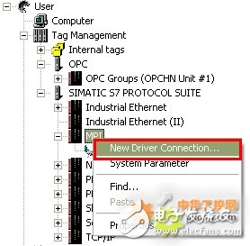
Figure 1.7
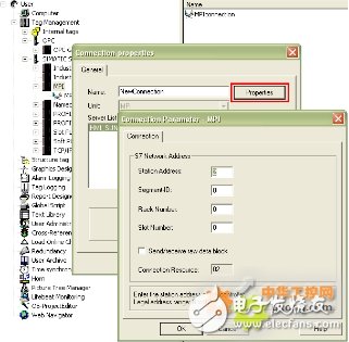
Figure 1.8
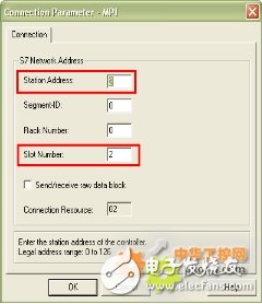
Figure 1.9
The important parameters are as follows:
Station Address: MPI port address
Rack Number: The rack number where the CPU is located. It is generally filled with 0 except for special and complicated use cases.
Slot Number: The slot number where the CPU is located
Note: If you are an S7-300 PLC, then the parameter is 2. If it is an S7-400 PLC, you must check which slot the PLC is inserted in according to the Hardware software in the STEP7 project. It cannot be installed based on experience and physical installation. Fill in the location at will, the possible parameters are 2, 3, 4 (mainly determined by the size of the power supply), otherwise the communication cannot be established.
6. Connection test and communication diagnosis
Through the channel diagnosis program WinCC Channel Diagnosis in the WINCC tool, you can test whether the communication is established.
Note: The PLC must be in the running state at this time, the old version of the PLC must be in the RUN-P or RUN state, and WINCC must be activated to run. According to the position shown in Figure 1.9, enter the channel diagnostic tool to check whether the communication is successfully established. As shown in Figure 1.10, the green "√" indicates that the communication has been successfully established.
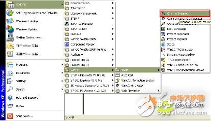
Figure 1.10
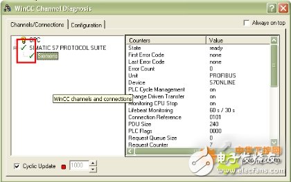
Figure 1.11
So far, the process of WINCC using the CP5611 communication card to connect to the PLC via MPI is complete.
two. WINCC uses CP5611 communication card to connect to PLC via PROFIBUS
Prerequisites
1. The prerequisite for the communication between the PLC system and WINCC6.0 through CP5611 is to install the CP5611 communication board on the computer with WINCC.
2. Set the port of the PLC to be connected to the PROFIBUS communication protocol, which is especially important for MPI/DP type ports.
I. STEP 7 hardware configuration
Use STEP 7 software to configure the hardware information of PLC, configure the corresponding board in Hardware for hardware configuration, select the corresponding port you will connect to WINCC, if the type is MPI/DP, you need to specify the port as PROFIBUS, as shown in the figure below 2.1 shows:
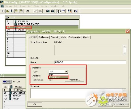
Figure 2.1
Click the Properties... button as shown in the figure above, as shown in the figure below:
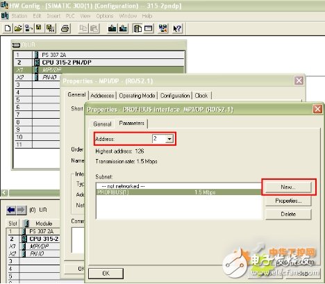
Figure 2.2
A. Set the address of the PROFIBUS port to 2
B. Click the New button to create a new PROFIBUS network under Subnet, and set the parameters in the pop-up dialog box, as shown in Figure 2.2:
The important parameters are as follows:
Highest PROFIBUS Address:
Refers to the highest station address in the entire PROFIBUS network, the default is 126, which can be modified.
Transmission Rate:
The communication rate of PROFIBUS network, the communication baud rate of all stations in the whole network should be the same.
Profile:
Specific transmission protocol settings, here we use DP.
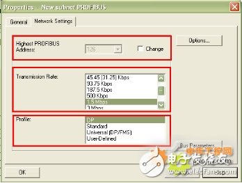
Figure 2.3
Other settings can be set according to the specific conditions of your project.
2. Install CP5611 communication board
Install CP5611 and install the driver. For the specific installation process and precautions of CP5611, please refer to the following link:
http://support.automation.siemens.com/WW/view/en/26707026
3. Add drivers and set system parameters
Open the WINCC project in Tag Management--"SIMATIC S7 PROTOCOL SUITE-"PROFIBUS
Right-click PROFIBUS, click System Parameter in the pop-up menu, as shown in Figure 2.4, the System Parameter- PROFIBUS dialog box will pop up, select the Unit tab, and view the Logic device name. After the default installation, the logical device name is CP_L2_1:, as shown in Figure 2.5:
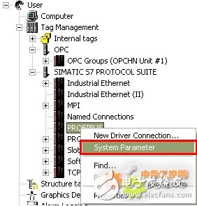
Figure 2.4
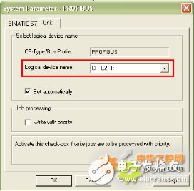
Figure 2.5
4. Set PG/PC Interface
Enter the control panel under the Windows operating system, double-click the Set PG/PC Interface icon, and select CP_L2_1 in the drop-down list of Access Point of the Application: as shown in Figure 2.6, and then in the list of Interface Parameter Assignment Used:, click CP5611 (PROFIBUS), and then displayed in the drop-down list of Access Point of the Application:: CP_L2_1: Ã CP5611 (PROFIBUS), as shown in Figure 2.7.
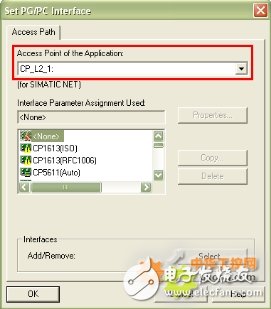
Figure 2.6
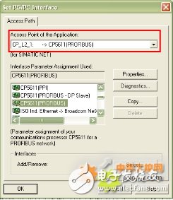
Figure 2.7
Set the communication parameters of CP5611, click Properties... Button to pop up Properties-CP5611 (PROFIBUS)
parameter. As shown in Figure 2.8:
The important parameters are as follows:
Address:
PROFIBUS address of CP5611
Transmission Rate:
The transmission rate of the PROFIBUS network (you can modify it, but it must be the same as the transmission rate of the PROFIBUS port actually connected to the PLC)
Highest Station Address:
The highest station address of the PROFIBUS network (must be the same as the PROFIBUS network parameter setting of the PLC)
Profile:
Set the specific communication protocol, use DP here
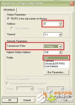
Figure 2.8
To diagnose the PROFIBUS network, click the Diagnostic... button to enter the diagnostic dialog box. As shown in the figure below: After the Test button is clicked, OK is displayed, indicating that the CP5611 is working normally. After clicking the Read button, the station addresses of all devices connected to the PROFIBUS network will be displayed. If you can only read your own station address, please check the PROFIBUS network and hardware connection settings at this time. Only the station address of the CPU is successfully read. , The following steps can be carried out, otherwise, it is impossible to establish communication, as shown in Figure 2.9:
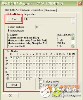
Figure 2.9
5. Add channel and connection settings
Add drive connection and set parameters. Open the WINCC project in Tag Management--"SIMATIC S7 PROTOCOL SUITE-"PROFIBUS, right-click PROFIBUS, in the drop-down menu, click New Driver Connection, as shown in Figure 2.10, click the Properties button in the pop-up Connection properties dialog box, The Connection parameters-PROFIBUS properties dialog box pops up, fill in the parameters, as shown in Figure 2.11:
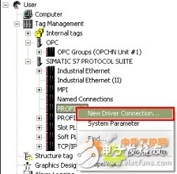
Figure 2.10
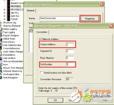
Figure 2.11
The important parameters are as follows:
Station Address: (IP address of the communication module)
Rack Number: The rack number where the CPU is located. It is generally filled with 0 except for special and complicated use cases.
Slot Number: The slot number where the CPU is located
Note: If you are an S7-300 PLC, then the parameter is 2. If it is an S7-400 PLC, you must check which slot the PLC is inserted in according to the Hardware software in the STEP7 project. It cannot be installed based on experience and physical installation. Fill in the location at will, the possible parameters are 2, 3, 4 (mainly determined by the size of the power supply), otherwise the communication cannot be established.
6. Connection test and communication diagnosis
Through the channel diagnosis program WinCC Channel Diagnosis in the WINCC tool, you can test whether the communication is established. Note: The PLC must be in the running state at this time, the old version of the PLC must be in the RUN-P or RUN state, and WINCC must be activated to run. According to the position shown in Figure 2.12, enter the channel diagnostic tool to check whether the communication is successfully established. As shown in Figure 2.13, the green "√" indicates that the communication has been successfully established.

Figure 2.12

Figure 2.13
So far, the process of WINCC using the CP5611 communication card to connect to the PLC via PROFIBUS is complete.
Annealing Machine,Pv Copper Strip Annealing Machine,Pv Copper Strip Annealing Equipment,Annealing Heat Treatment Machine
Jiangsu Lanhui Intelligent Equipment Technology Co., Ltd , https://www.lanhuisolar.com
