
With the development of the times and technology, the requirements for data bus bandwidth are getting higher and higher, and it is increasingly difficult for the existing bus standards to meet the requirements for high bus speeds in practical applications. Advanced bus technology plays a vital role in solving system bottlenecks and improving system performance. At the same time, in order to realize batch data transmission, IEEE has announced IEEE Std 1394b-2002 (1394b) serial that supports higher transmission rates. Bus standard, high-speed upgradeability can support data transfer rates up to 800 Mb/s, and can be backward compatible with the previous 1394-1995 and 1394a standards. Since 1394b is a serial bus standard with a higher data transmission rate, it supports two transmission modes: asynchronous transmission and isochronous transmission. The layered software and hardware model enables its communication to be established on the basis of transaction layer, link layer and physical layer protocols. This article makes full use of the hardware resources of FPGA and DSP chips, and based on the 1394b transmission protocol and specifications, introduces the hardware design structure of the 139 4b data transmission system, the system's work flow and the configuration process of the bus.
1 Features of 1394bThe main features of 1394b two-way data transmission system are as follows:
(1) High-speed upgradeable: support transmission rates of 100 Mb/s, 200 Mb/s, 400 Mb/s and 800 Mb/s, which can be increased to 3.2 Gb/s when using plastic optical fiber;
(2) Support point-to-point transmission: each node can perform transactions independently from the host;
(3) Plug and play: You can add or remove devices to the 1394b network at any time. There is no need to worry about affecting data transmission or reconfiguration. The bus will be re-enumerated, and the nodes can also be automatically configured. Host intervention
(4) Hot swap: Add or remove devices without powering off the system;
(5) Transmission distance: When using CAT-5UTP5 cable (category 5 unshielded twisted pair), the transmission rate can be guaranteed to extend the transmission distance to 100 m under the premise of 100 Mb/s. When glass optical fiber is used, it can be at 3.2Gb Extend to 50 m under the premise of /s;
(6) Two transmission methods are supported: including isochronous and asynchronous data transmission methods;
(7) Topological structure: The tree or daisy chain topology structure is adopted between the devices, and each bus can connect up to 63 devices;
(8) Power supply available: some low-power devices can obtain power through the bus without having to configure an independent power supply system for each device;
(9) Fair arbitration: Isochronous transmission has a higher priority, while asynchronous transmission can also obtain fair access to the bus;
(10) Improve system performance: Regard resources as registers and memory units, read/write operations can be performed according to the transmission rate of CPU memory, so it has high-speed transmission capabilities.
2 The hardware realization of 1394b data transmission systemBecause the 1394b link layer chip must be connected to the FPGA through a PCI bus interface to realize data transmission. If you only use FPGA and DSP to control PCI peripherals, you need to design complex interface logic. In the 1394b high-speed data transmission system, it will not only affect the performance of the FPGA itself, but also bring many circuits or systems outside the FPGA. problem. Therefore, the PCI9054 bus interface chip is used here with FPGA and DSP to realize the 1394b two-way data transmission system, which converts the control of the complex PCI bus interface to the control of the relatively simple local bus interface. It not only has good support for the PCI protocol, but also Provide a good interface to the designer, greatly reducing the designer's workload. The PCI9054 chip supports 32-bit/33 MHz on the PCI bus side. When the local bus side uses a 32-bit data bus, its data transfer rate can reach 132 MB/s, so it can meet the data transfer rate requirement of 800 Mb/s on the 1394b bus. .
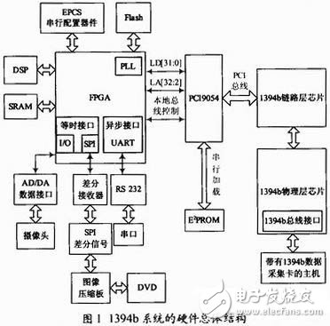
The main control chip in this design uses Altera's EP2C70F672C6 FPGA mainstream chip, DSP uses TI's TMS320C6415 DSP chip, 1394b set uses TI's link layer chip TSB82AA2 and physical layer chip TSB81BA3, and PCI9054 uses PLX's 32 It is a 33MHz PCI bus universal interface chip. The overall hardware structure of the 1394b bidirectional data transmission system is shown in Figure 1. It is mainly composed of a field programmable gate array (FPGA) module, a DSP module, an AD/DA data conversion interface module, an SPI data input/output interface module, and a serial port (UART ) Communication module, SRAM storage module, EPCS serial configuration device module, FLASH storage module, PCI9054 module and 1394b chip module.
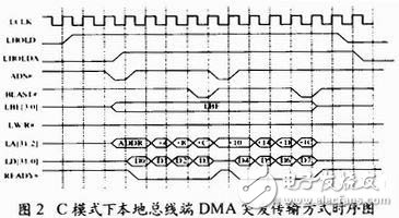
Due to the existence of the programmable FIFO memory in the PCI9054, data can be transmitted in large batches without loss. This does not meet the real-time requirements. At the same time, the local clock asynchronous with the PCI clock can be used according to the needs of the user. The PCI9054 local bus works in In the C mode, the PCI data line and the address line are separated through the logic control in the chip, which conveniently provides various methods for the working sequence of the local bus. Figure 2 shows the timing diagram of the local bus data burst DMA transmission mode of PCI9054 connected to FPGA in C mode. Among them, LCCLK is the input clock signal. It can be seen from Figure 2 that data is read and written on the local bus When the data cannot be continuously transmitted, the waiting state can be inserted, which can greatly improve the data throughput.
Since the 1394b bus standard supports two types of sub-transactions, isochronous sub-transactions and asynchronous sub-transactions, the type of data transmitted is divided into isochronous data and asynchronous data. Isochronous transmission transfers an indefinite amount of data to a certain time interval at a specified time interval. Address transmission requires high real-time performance and does not need to return confirmation signals; while asynchronous transmission is to transmit data to a specific address, which requires high accuracy of data transmission, and requires the receiving end to send back confirmations in the form of multiple handshake. signal. In this system, the data sent by the DVD player is compressed by the image compression board and then transferred to the FPGA through the SPI port, or the data sent by the camera is converted by A/D, and then sent to the FPGA by the general I/O port of the FPGA. These are all isochronous data; and some asynchronous data such as control commands are sent to the FPGA from the serial port and processed by the DSP. The combination of DSP and FPGA can improve the efficiency of data transmission. FPGA realizes serial-to-parallel conversion of data and data splicing, and packs the data into a data packet type conforming to the 1394b protocol and the header information of the configuration data packet, which passes through the read/write FIFO and buffers in the external SRAM, and arbitrates through the DMA arbitration module Processing, use the fast data transfer mechanism of DMA to write data into the FIFO of PCI9054. PCI9054, as a bridge chip, provides information transfer between the local bus and the PCI bus. The PCI9054 chip converts the local data bus standard into a PCI bus data standard that can be transmitted by the 1394b link layer chip, and then passes through the 1394b link The layer chip realizes the decoding of the address and channel number of the isochronous and asynchronous data packets, data verification, data analysis, etc. Finally, the physical layer chip realizes the access to the bus through the arbitration logic, and carries out the data to be sent by the local node. Encoding, the electrical and mechanical interface provided by the physical layer chip sends the data bits to the 1394b cable connected to it, and finally sends it to the host connected to the 1394b board to decompress and play the data sent by the DVD to send to the camera Play and display asynchronous data and other operations. The read data is sent by the host connected to the 1394b board, and processed through the 1394b physical layer chip, 1394b link layer chip, FPGA, external SRAM, etc., and sent out from the corresponding port according to the data packet type. During this period, the opposite operation was performed compared with sending data, thus realizing the 1394b two-way data transmission system.
As the control and management module of the entire system, FPGA mainly completes the following tasks:
(1) Send and receive data from SPI port, UART port and AD/DA port;
(2) Serial-to-parallel conversion and data splicing of the data to be sent;
(3) Pack and unpack the data and cache the data through SRAM;
(4) Communicate with PCI9054 chip to complete data transfer.
The main functions of DSP in this system are:
(1) Communicate with PCI9054 chip and 1394b link layer chip to realize device bootstrapping and identity confirmation;
(2) Send and receive some control commands to control the transmission of data;
(3) Realize the function of sending and receiving asynchronous data, and deal with it according to the type of asynchronous request data;
(4) Apply for isochronous channel and bandwidth for isochronous transmission, and release the requested channel and bandwidth after transmission.
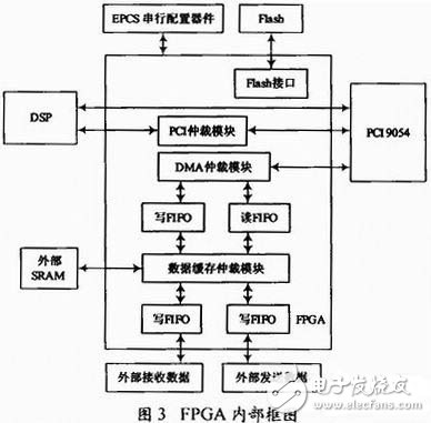
Figure 3 shows the internal block diagram of the FPGA in the system. Due to the fast data transmission rate, data processing requires a certain amount of time, and each group of data cannot be transmitted uninterruptedly, and the internal FIFO of the FPGA has limited capacity. SRAM and FPGA are used. Combined to complete the buffering of input and output data; DSP implements some auxiliary operations such as processing asynchronous data, configuring the internal registers of the PCI9054 chip and 1394b link layer registers, etc., as well as PCI transmission control, device identification, and applying for channels for isochronous transmission And bandwidth, etc.; EPCS serial configuration chip realizes the storage of configuration data, so that after the system is powered on, the configuration data is automatically downloaded to the FPGA. At the same time, FLASH memory can be used to store DSP user code. After the DSP is powered on, use the DSP provided Boot mechanism, and then download the program to DSP RAM, so that the system can work offline.
The configuration of the 1394b bus is automatic, and it is not subject to interference from any device or host. There are three main steps in the bus configuration process:
(1) Bus initialization;
(2) Self-identification;
(3) Tree identification.
After these three processes, the entire system logically forms a tree-like topology, and each node is assigned a node number and sends out node description information. The initialization process of the bus is as follows:
(1) Equipment identification: equipment identification can be done through E2PROM;
(2) Allocate I/O space and Memory space;
(3) Configure the DMA register of PCI9054;
(4) Configure the 1394b link layer and physical layer chips.
Because the 1394b OHCI (Open Host Control Interface SpecificaTIon) protocol is an implementation of the 1394b serial bus link layer protocol. The 1394bOHCI protocol stipulates that the isochronous transmission and asynchronous transmission of 1394b are both DMA methods, so it is necessary to configure the DMA register of PCI9054. There are two independent channels in PCI9054 that use DMA to transfer data without the intervention of the host. At the same time, using burst mode to transfer data can increase the data transfer rate, and at the same time can give full play to the performance of the PCI bus.
After the system is powered on, it is usually necessary to perform device bootstrapping to assist the host in completing device identification and device identity confirmation. The bootstrapping of the device mainly includes: initializing link layer registers; initializing configuration ROM; judging whether the cable is inserted; forcing the root node; Respond to the root node and read the configuration ROM request until the root node calls the corresponding driver to complete the device identification. Figure 4 shows the working flow chart of this system.
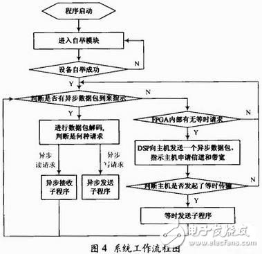
After the device bootstrapping is completed, it can wait for the arrival of the data packet. According to the type of the data packet, if it is an asynchronous data packet, the corresponding processing will be performed; if it is an isochronous data packet, the application for isochronous channel and bandwidth will be performed. After the application is successful Configure the DMA register to send isochronous data or receive isochronous data in DMA mode, and release its channel and bandwidth after isochronous data transmission is completed, so that one data transmission is completed, and then the next data transmission is performed, and so on. Complete the entire data transmission.
5 concluding remarksAs a platform-independent technology, IEEE 1394b can be used in MAC and PC at the same time. The main content of this paper is to use FPGA, DSP and PCI9054 chip to realize 1394b data transmission system. At present, China basically still stays at the transmission of 1394 or 1394a bus data. This system is based on the predecessors to realize the data transmission on the 1394b bus. At the same time, the system is compatible with 1394a to realize 1394 transmission, and the transmission rate can be increased. As a universal platform for verifying the 1394b protocol, 1394b can provide a transmission speed of 800 Mb/s or higher. Although there is no optical storage product with a 1394b interface on the market, it is believed that it will inevitably appear in front of users in the near future, whether it is In terms of video transmission or computer peripherals, network interconnection, etc., there will be a broad market.
Capillary Thermostat,Water Heater Thermostat,Electric Water Heater Capillary Thermostat,Hot Water Heater Thermostat
Foshan City Jiulong Machine Co., Ltd , https://www.jlthermostat.com