The main function of the TL431 is to make the circuit obtain a more stable voltage, and the TL431 is a more precise controllable voltage source with a relatively special dynamic impedance. Its fast dynamic response, low output noise, and low price.
Note that the above sentence is summarized as a cheap, precise and controlled voltage source TL431.
The output voltage of the TL431 can be arbitrarily set to voltages from 2.5V to 36V through two resistors. The operating current can be from 0.1 to 100mA and the output voltage ripple is low.
Several common usages are as follows:
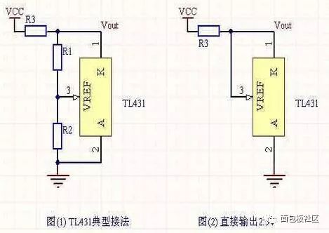
In the figure above, REF is the reference, Anode is the anode, and CATHODE is the cathode. Since the TL431 comes with a 2.5V reference source internally, a fixed voltage value is output for the TL431 connection method in (1). The formula is: Vout = (R1+R2)*2.5/R2, and the value of R3 should satisfy 1mA. < (Vcc-Vout)/R3 <500mA. When R1 takes 0, R2 can be omitted. At this time, the circuit becomes the form of (2). The TL431 is equivalent to a 2.5V regulator.
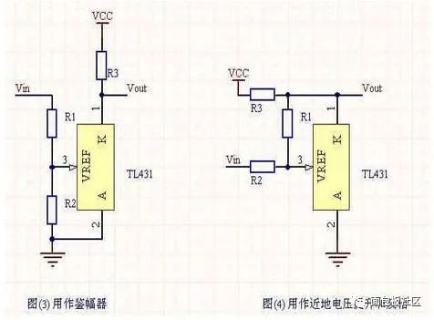
The TL431 can also be used to form a scope, as shown in (3). This circuit outputs Vout when the input voltage Vin < (R1+R2)*2.5/R2 is high, whereas the output is close to 2V. It should be noted that when Vin fluctuates in a small range around (R1+R2)*2.5/R2, the circuit will output an unstable value.
The TL431 can be used to boost a near-ground voltage and invert it. As shown in (4), the output calculation formula is: Vout = ((R1+R2)*2.5 - R1*Vin)/R2.
When R1 = R2, Vout = 5 - Vin. This circuit can be used to raise a near-ground voltage to a pre-set range. The only thing to notice is that the TL431's output range is not full.
The TL431 itself has a fairly high gain (I roughly tested it in the simulation, about 46db) so it can be used as an amplifier.
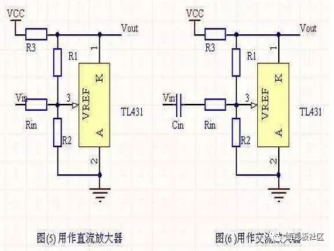
Figure (5) shows a DC voltage amplifier composed of TL431. The amplification of this circuit is determined by R1 and Rin. It is equivalent to the op amp's negative feedback loop, and its static output voltage is determined by R1 and R2. The advantage of this circuit is that it has a simple structure and good accuracy, and can provide stable static characteristics. The disadvantage is that the input impedance is small and the Vout swing is limited.
Figure (6) is an AC amplifier. This structure is similar to the DC amplifier and has the same advantages and disadvantages.
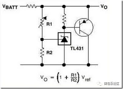
The figure above is a large current shunt regulator circuit.
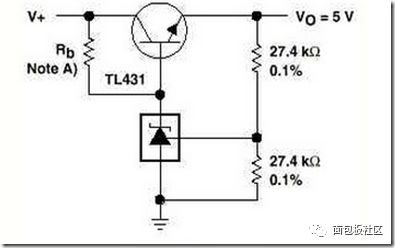
Precision 5V output.
Shenzhen MovingComm Technology Co., Ltd. , https://www.movingcommtech.com
