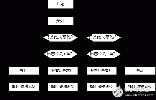
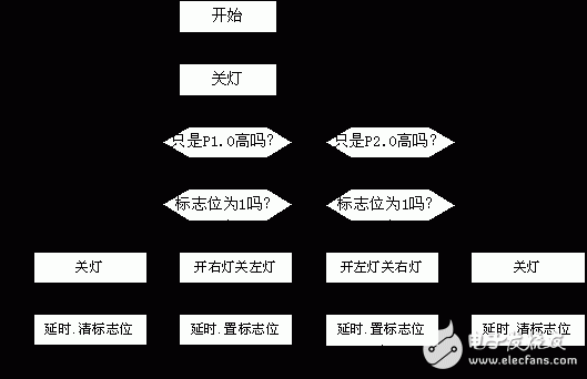
When the P1.0 switch is connected to 5V, the right turn light flashes, and when the P1.1 switch is connected to 5V, the left turn light flashes. When the P1.0 and P1.1 switches are connected to 5V or grounded at the same time, the cornering lights are not flashing.
Block diagram
When the P1.0 switch is connected to 5V, the right turn light flashes, and when the P1.1 switch is connected to 5V, the left turn light flashes.
When the P1.0 and P1.1 switches are connected to 5V or grounded at the same time, the cornering lights are not flashing.
Block diagram


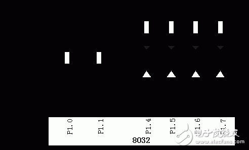
P1.0, P1.1 are connected to a certain two digits of the toggle switch JP40, P1.4 ~ P1.7 are connected to a certain four bits of the LED indicator JP32, and the program is continuously run; the turn light should be seen to be correct. The delay subroutine needs to be modified when debugging the program in a single step (for example, the first byte of the delay program can be changed to the return instruction 22H).
programORG 0C30H
0C30 7590EF PX00: MOV P1, #0FFH; Initialization
0C33 E590 PX03: MOV A, P1
0C35 F5F0 MOV B, A
0C37 5403 ANL A, #03H
0C39 B40126 CJNE A, #01H, PX01; Is it just a high condition for P1.0?
0C3C 200012 JB 00H, PX04 ; flashing flag
0C3F C294 CLR P1.4
0C41 C295 CLR P1.5; turn right light
0C43 D296 SETB P1.6
0C45 D297 SETB P1.7; turn left light
0C47 7A20 MOV R2, #20H
0C49 120213 LCALL DELY; delay
0C4C D200 SETB 00H ; set flag
0C4E 020C33 LJMP PX03; continue to check status
0C51 D294 PX04: SETB P1.4
0C53 D295 SETB P1.5
0C55 D296 SETB P1.6; turn off the light
0C57 D297 SETB P1.7
0C59 7A20 MOV R2, #20H
0C5B 120213 LCALL DELY; delay
0C5E C200 CLR 00H ; clear flag
0C60 8133 AJMP PX03; continue to check status
0C62 B40227 PX01: CJNE A, #02H, PX02; meets only the high condition of P1.1
;?
0C65 200112 JB 01H, PX05;
0C68 D294 SETB P1.4
0C6A D295 SETB P1.5; turn left light
0C6C C296 CLR P1.6
0C6E C297 CLR P1.7; turn right light
0C70 7A20 MOV R2, #20H ; Delay
0C72 120213 LCALL DELY
0C75 D201 SETB 01H ; set flag
0C77 020C33 LJMP PX03; continue to check status
0C7A D294 PX05: SETB P1.4
0C7C D295 SETB P1.5
0C7E D296 SETB P1.6; turn off the light
0C80 D297 SETB P1.7
0C82 7A20 MOV R2, #20H
0C84 120213 LCALL DELY; delay
0C87 C201 CLR 01H ; clear flag
0C89 020C33 LJMP PX03; continue to check status
0C8C D294 PX02: SETB P1.4
0C8E D295 SETB P1.5
0C90 D296 SETB P1.6; turn off the light
0C92 D297 SETB P1.7
0C94 020C33 LJMP PX03; continue
ORG 0213H
0213 C002 DELY: PUSH 02H
0215 C002 DEL2: PUSH 02H
0217 C002 DEL3: PUSH 02H; delay
0219 DAFE DEL4: DJNZ R2, DEL4
021B D002 POP 02H
021D DAF8 DJNZ R2, DEL3
021F D002 POP 02H
0221 DAF2 DJNZ R2, DEL2
0223 D002 POP 02H
0225 DAEC DJNZ R2,DELY
0227 22 RET
Experimental phenomena and conclusions Experimental phenomena:Stainless Steel Isolation Pressure Core
Stainless Steel Isolation Pressure Core,Motion Sensor System,Water Sensor Switch,Water Sensor
Shenzhen Ever-smart Sensor Technology Co., LTD , https://www.fluhandy.com
