
This example realizes the control of the keyboard, LCD, RS-232 interface or device on the Red Hurricane II Xilinx development board through Verilog programming. The data input by the keyboard is displayed on the LCD, or through RS-232 in the PC. It is displayed on the HyperTerminal on the machine.
2. Example goalThrough this example, the reader should achieve the following goals.
Learn about the PS/2 interface protocol.
Master the working principle of the keyboard.
Write the Verilog program to read the keyboard input information through the PS/2 interface on the development board.
Principle introduction
The PS/2 keyboard fulfills a two-way synchronous serial protocol. In other words, one bit of data is sent each time on the data line, and every time a pulse is clocked on the clock line, the keyboard can send data to the host, and the host can send data to the device. But the host always has priority on the bus, it can suppress communication from the keyboard at any time, just pull the clock down.
This example is to write a Verilog program that implements PS/2 port functionality. First, we need to understand the structure and pin function definition of the PS/2 port, as shown in Table 1.
Table 1 PS/2 port structure and pin definition
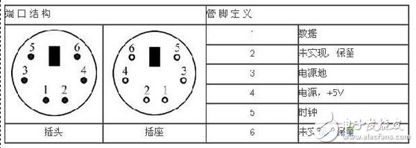
It can be seen that there is only one data port in PS/2. To distinguish many buttons, an efficient resolution method is needed. The keyboard's processor spends a lot of time scanning or monitoring the button matrix. If it finds that a key has been pressed, releasing or holding the keyboard, a packet of the scan code will be sent to the computer.
There are two different types of scan codes: "pass code" and "break code". A "pass code" is sent when a key is pressed or pressed, and a "break code" is sent when a key is released. Each button is assigned a unique "pass code" and "break code". In this way, the host can determine which button is pressed by looking for a unique scan code.
A complete set of on-off codes for each key constitutes the scan code set. Figure 1 contains the scan codes for most of the keys on the keyboard.
When the button is released, the keyboard returns a "F0" in front of the scan code as the button release signal. At the same time, some buttons are Extended. In this case, an "E0" is added to the front of their scan code. When the button is released, "E0F0" will be added to the front of the scan code.
Let's take a look at how the signal is input from the keyboard through the data line of the PS/2 port. First, the keyboard should check whether the data line and the clock line are both high. Only when they are in a high state can the data be written. Data sent from the keyboard to the host is read on the falling edge of the clock signal (when the clock changes from high to low).
The keyboard mainly uses a serial protocol that contains 11 bits per frame: the first bit is the start bit, always "0"; the next is the 8-bit data bit, the order is from low to high; then the parity is followed The position is checked; the last is the end bit, which is always "1". A timing diagram of the protocol is shown in Figure 2.
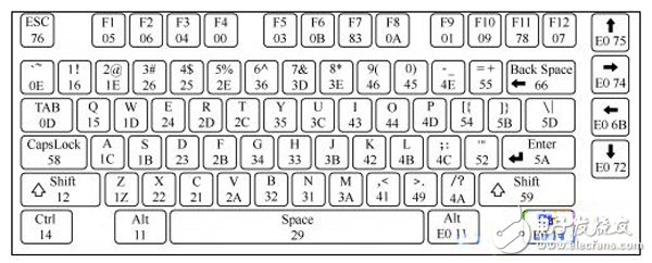
Figure 1 keyboard scan code

Figure 2 keyboard serial protocol
Detailed example
Only the main operational procedures are given here.
(1) Start the ISE software.
(2) Create a new project.
(3) Write a keyboard serial protocol.
Write the corresponding Verilog code according to the timing of Figure 2. See the example code for the specific source code.
(4) Add design input.
The prepared interface protocol is loaded into the project, and the interface control and the system are connected.
(5) Set device and pin constraints.
Follow the instructions on the development board to make the relevant settings.
(6) Download verification.
After downloading the program, connect the keyboard to the development board, and you can see the characters entered by the keyboard through the LCD of the development board.
Steel Wire Armored Underground Power Cable
Standard: BS 5467 BS 6346 IEC 60502
Rated Voltage: 0.6/1kV
Armour:
Single Core: AWA (Aluminium Wire Armour)
Multi-Core: SWA (Steel Wire Armour)
Certificates: Third party test reports
Applications: Armored Cable for power networks, industrial plants, switch-boards, underground and in cable ducting where better mechanical protection is required.
Swa Cable,Armoured Cable,Steel Armoured Cable,Outdoor Armoured Cable
Shenzhen Bendakang Cables Holding Co., Ltd , https://www.bdkcables.com