
For a long time, single-chip microcomputers have been widely used in various fields due to their unique advantages such as high performance-price ratio, small size, flexible function, high reliability, easy human-machine dialogue and good data processing capability. However, due to its internal resources, in many applications, microcontrollers need to extend related resources off-chip, such as program memory, data memory, I/O ports, and interrupt sources. With the development of programmable logic devices (PLDs) and EDA technologies, FPGA/CPLD is often used in system design to expand the related resources of microcontrollers, so that they can be organically combined to shorten the development cycle and meet market needs. FPGA/CPLD has the advantages of high speed, high reliability, convenient development and specification, and it has strong complementarity with the single chip in function. The circuit structure combining these two types of devices is widely used in many high-performance instrumentation and electronic products. Based on this demand, the author designed the bus interface logic circuit of MCS51 MCU and FPGA/CPLD, realized the reliable communication between MCU and FPGA/CPLD data and control information, and made FPGA/CPLD and MCU complement each other to form flexible, hardware and software. A field-programmable control system.
1 interface mode between single chip microcomputer and FPGA/CPLDThere are two kinds of interface modes between single chip microcomputer and FPGA/CPLD, namely bus mode and independent mode.
1.1 bus modeThe MCS51 MCU has a strong external bus expansion capability. It is easy to implement the bus interface between the MCU and the FPGA/CPLD by using the off-chip three-bus structure (ie, data bus, address bus, and control bus). The basic principle block diagram is shown in Figure 1.
Figure 1 bus mode block diagram
The logic design of the MCU and FPGA/CPLD communication in the bus mode, it is important to understand the bus read and write timing of the MCU in detail, and design the logic structure according to the timing diagram. The timing of the communication must follow the fixed bus mode read/write timing in the MCU. . The logic design of FPGA/CPLD is also relatively complicated. In programming, it must be combined with the interface microcontroller program to strictly arrange the I/O space that the microcontroller can access. However, there are many advantages to the microcontroller's data and control information communication with the FPGA/CPLD in the bus mode:
â—† Fast speed. The communication working sequence is pure hardware behavior. For the MCS51 microcontroller, only one single-byte instruction can complete the required read/write timing, such as "MOV @DPTR, A" and "MOV A, @DPTR".
â—† Save the I/O line of the PLD chip. Only through 19 I/O lines can exchange various types of data and control information between the FPGA/CPLD and the microcontroller.
â—† Compared with the non-bus mode, the MCU programming is simple and reliable.
â—† Through logic switching in CPLD/FPGA, the microcontroller can easily interface with SRAM or ROM. This method has many practical applications. For example, using a DMA working method similar to a microprocessor system, high-speed data sampling is first performed by the FPGA/CPLD and the interface high-speed device, and the data is temporarily stored in the SRAM. Through the switching, the MCU and the SRAM are used for data communication in the bus mode, so as to exert the powerful data processing capability of the MCU.
Different from the bus interface mode, almost all single-chip microcomputers can communicate with the FPGA/CPLD in a separate interface mode, and the timing mode of communication can be freely determined by the designed software, and the form is flexible and diverse. The biggest advantage is that the interface logic in the FPGA/CPLD does not need to follow the read/write timing of the fixed bus mode in the microcontroller. The logic design of the FPGA/CPLD and the microcontroller programming of the interface can be completed relatively independently. In fact, many popular microcontrollers currently have no bus operation, and they can be combined with FPGA/CPLD in an independent manner. The independent interface design method is relatively simple, and its basic principle block diagram is shown in Figure 2. Directly connect the I/O port line of the MCU to the I/O of the FPGA/CPLD.
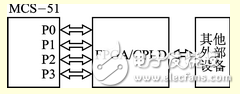
Figure 2 Block diagram of the independent mode
2 bus interface logic designSince the MCU has many advantages in data and control information communication with the FPGA/CPLD in the bus mode, in the design, the MCU and the FPGA/CPLD interface adopt the bus mode.
2.1 Interface design ideasFor the logical interface design of MCS51 MCU and FPGA/CPLD in bus mode communication, the bus read/write timing of MCS51 MCU should be understood in detail, and the logic structure should be designed according to the timing chart. The timing of the MCS51 microcontroller bus read/write is shown in Figure 3. The timing change speed is related to the operating clock frequency of the microcontroller.
Figure 3 MCS51 microcontroller bus read / write timing
CLK is the microcontroller clock signal, and ALE is the address latch enable signal. After the start of the read/write cycle, the CPU sends the lower 8-bit address to the P0 port bus, the upper 8-bit address to the P2 port bus, and the lower 8-bit address is latched into the address latch using the ALE falling edge. The upper 8 bits of the address information are always latched in the P2 port latch; at the same time, the MCU uses the read command to enable the low level of the signal PSEN to read the instruction from the ROM port in the ROM, and the timing of the instruction read is at PSEN. Before the rising edge. Next, the upper 8 bits and the lower 8 bits of the data address are respectively outputted by the P2 port and the P0 port, and the lower 8 bit address of the P0 port is latched to the address latch by the falling edge of the ALE. Then read and write external data according to the state of the read/write signal, and send the data to the P0 port bus; the data read/write timing is to read the data into the MCU or write the addressed address before the rising edge of the read/write signal. Address unit. When the read/write signal becomes inactive, the P0 port bus becomes floating and ready for the next bus read/write.
Power Meter is a monitoring and testing instrument which determines the power consumption of a connected appliance and the cost of the electricity consumed.
Built-in 3.6V rechargeable Batteries ( . The purpose of the batteries is to store the total electricity and memory setting
Resetting
If an abnormal display appears or the buttons produce no response, the instrument must be reset. To do this,
press the RESET button.
Display Mode
Entire LCD can be displayed for about 1 minute and then it automatically gets into Model. To transfer from
one mode to the other, press the FUNCTION button.
Mode 1: Time/Watt/Cost Display Display duration(how long) this device connect to power source.LCD on first line shows 0:00 with first two figures mean minutes(2 figures will occur while occur at 10 min) and the rest shows seconds. After 60mins, it displays 0:00 again with first two numbers meas hour(2 figures will occur at 10hours)and the rest shows minutes. The rest can be done in the same manner which means after 24 hours, it will re-caculate. LCD on second line displays current power which ranges in 0.0W 〜 9999W. LCD on third line displays the current electricity costs which ranges in O.Ocost 〜 9999cost. It will keep on O.OOcost before setting rate without other figures.
Mode 2: Time/Cumulative electrical quantity Display Display duration(how long) this device connect to power source.
LCD on first line shows 0:00 with first two figures mean minutes(2 figures will occur while occur at 10 min) and the rest shows seconds. After 60mins, it displays 0:00 again with first two numbers meas hour(2 figures will occur at 10hours)and the rest shows minutes. The rest can be done in the same manner which
means after 24 hours, it will re-caculate. LCD on second line displays current cumulative electrical quantity which ranges in 0.000KWH 〜 9999KWH without other figures. LCD on third line displays"DAY"- "1 'Will be showed on numerical part(the other three figures will be showed at carry) which means it has cumulated electrical quantity for 24hours(one day). The rest can be done in the same manner untill the maximal cumulative time of 9999 days.
Mode 3: TimeA^bltage/Frequency Display LCD on first line displays the same as Mode 1 dones. LCD on second line displays current voltage supply (v) which ranges in 0.0V 〜 9999V .LCD on third line displays current frequency (HZ) which ranges in 0.0HZ 〜 9999Hz without other figures.
Mode 4: Time/Current/Power Factor Display LCD on first line displays the same as Mode 1 dones.LCD on second line displays load current which ranges in 0.0000A 〜 9999A. LCD on third line displays current power factor which ranges in 0.00PF 〜 LOOPF without other figures.
Mode 5:Time/Minimum Power Display LCD on first line displays the same as Mode 1 dones. LCD on
second line displays the minimum power which ranges in 0.0W 〜 9999W. LCD on third line displays character of "Lo" without other figures.
Mode 6: Time/Maximal Power Display LCD on first line displays the same as Mode 1 dones. LCD on second line displays the maximal power which ranges in 0.0W 〜 9999W. LCD on third line displays character of "Hi" without other figures.
Mode 7: Time/Price Display LCD on first line displays the same as Mode 1 dones. LCD on third line displays the cost which ranges in O.OOCOST/KWH 〜 99.99COST/KWH without other figures.
Overload Display: When the power socket connects the load over 3680W, LCD on second line displays the''OVERLOAD[ with booming noise to warn the users,( 1918928,selectable choice)
Supplemental informations:
1: Except [OVERLOAD[ interface, LCD on first line display time in repitition within 24hours.
2: LCD on first line, second line or third line described in this intruction take section according to two black lines on LCD screen. Here it added for clarified purpose.
3. Mode 7 will directly occur while press down button "cost".
4. [UP"&"Down" are in no function under un-setting mode.
Setting Mode
1. Electricity price setting
After keeping COST button pressed lasting more than 3 seconds(LCD on third line display system defaults price, eg O.OOCOST/KWH ),the rendered content begins moving up and down which means that the device
has entered the setting mode. After that, press FUNCTION for swithing , then press "UP"and "DOWN" button again to set value which ranges in OO.OOCOST/KWH 〜 99.99COST/KWH. After setting all above, press COST to return to Mode7 or it will automatically return to Mode7 without any pressing after setting with data storage.
LCD Display Power Meter Socket,Power Meter Plug Outlet,Electricity Usage Monitor Socket,LCD Energy Power Meter Socket,Digital LCD Power Meter Socket
NINGBO COWELL ELECTRONICS & TECHNOLOGY CO., LTD , https://www.cowellsockets.com