
The fault current of the short circuit between the turns flows through the transformer, and the external current transformer usually has no obvious reaction. If the transformer's heavy gas protection action is correct and the fault recording analysis indicates that there is no internal phase or ground fault, it can be concluded that an inter-turn short circuit occurs internally. For the step-down transformer, it is assumed that a short circuit occurs on the power supply side, the short-circuited winding no longer flows through the primary current, the equivalent number of turns on the power supply side decreases, and the ratio decreases. Since the voltage on the power supply side is regarded as constant, the load side voltage rises. . On the contrary, if the load side is short-circuited between turns, the load side voltage drops and the load current decreases.
Due to the need of reactive power compensation, station power, etc., the current power grid widely uses three-winding and above transformers. When a multi-winding transformer has a turn-to-turn short circuit on one load side, not only the fault side voltage will be reduced because the windings are coupled with each other. The voltage on the non-faulty load side will also decrease, as evidenced by the accident case. The impedance of the external load of the transformer is constant before and after the occurrence of the turn-to-turn short circuit. The load current is proportional to the bus voltage. However, if the winding is connected to a triangle, there may be a zero-sequence current component inside the triangle when a turn-to-turn short circuit occurs. The load current may not be calculated. Winding current, and for the case where there is no multi-main transformer parallel operation on the load side, the voltage of each winding can be calculated according to the bus voltage, so it is more feasible to analyze the winding voltage than to analyze the current. At present, domestic and foreign research rarely analyzes the voltage influence of the inter-turn short circuit, and the internal fault analysis and calculation of the transformer is still the research focus of relay protection.
Taking the three-winding step-down transformer as an example, this paper analyzes the characteristics of the low-voltage winding turn-to-turn short circuit, establishes the equivalent model, and derives the voltage formula after the fault. The formula can not only calculate the fault information, but also prove that it is relative to the non-fault. On the pressure side, the voltage drop on the low voltage side where the fault occurs is more serious. Finally, this paper cites an example. The short-circuit point of a short-circuit accident in a turn is successfully judged by the formula of this paper. The example is simulated by Matlab. The simulation results prove that the formula is correct and has practical value.
The low-voltage side current is converted to the primary side for 1åŒ short-circuit modeling. 1.1 The load side turn-to-turn short circuit equivalent circuit is analyzed by taking the inter-turn short circuit of the low-voltage winding of the three-winding step-down transformer as an example, assuming that the load on the medium-voltage side is friend 2, Low-voltage side with load 3, short-circuit between the low-voltage windings, the short-circuit resistance is the brother, assuming that the ratio of the number of turns and the total number of turns is m (0 separately consider the low-voltage winding, the low-voltage side is short-circuited and not The shorted windings are treated as two different power supplies with internal resistance, respectively, and the circuit diagram on the low voltage side is shown.
Apply the superposition theorem to make the load current all equivalent to the primary side.
It is assumed that the induced voltage of the short-circuited winding is zero, and the induced current generated in the un-winding winding is equivalent to the primary side. In the re-assumed, the induced voltage of the short-circuited winding is zero, which is generated in the short-circuited winding. The induced current is equivalent to the current on the primary side (3), which is obviously the current of the two parallel circuits. Therefore, when the low voltage winding is short-circuited between turns, the circuit diagram of the three-winding transformer equivalent to the primary side is as shown.
It can be seen that the low-voltage winding inter-turn short circuit, the medium voltage side, the non-fault low-voltage side, and the fault voltage side are equivalent in parallel with the three load side equivalent impedances, and the short-circuited low-voltage winding and the un-short-circuited low-voltage winding are respectively equivalent. The two windings have a ratio of k13/m and k13/(1-m), respectively. The three-winding transformer is considered as a four-winding transformer, including a high-voltage side, a medium-voltage side, a short-circuited low-voltage side, and a low-voltage side that is not short-circuited. 1.2 Voltage drop after fault The output voltages of the medium and low voltage sides are the voltages of Zl2 and Zl3, respectively. For the convenience of calculation, the large impedance of the parallel circuit and the small impedance of the series circuit are appropriately ignored, which is simplified as Shown.
The simplified diagram of the inter-turn short circuit of the low-voltage winding of the three-winding transformer is based on the superposition theorem. After the inter-turn short circuit occurs on the low-voltage side, the center point voltage of the equivalent circuit diagram of the transformer after the fault is calculated, and the voltage at the center point is 'where, after the fault, the voltage on the low-voltage side is The voltage across the load.
The sub-mZ3â–¡R'T is the voltage-to-voltage drop ratio of the low-voltage side winding of the transformer.
The voltage drop ratios au2 and au3 on the medium and low voltage side before and after the accident are satisfied, and U2 and U3 are the medium and low voltage side voltages before the accident.
In equation (6), only two unknowns m and R' are included. The load parameters do not change before and after the fault. The calculated value before the fault can be taken. The transformer parameters also take the parameters before the fault, which can be calculated from the value given on the transformer nameplate. Obtained, substituting equation (6) can calculate m and R'. Let m=0, R'=~, the middle and low voltage windings have only one equivalent impedance kf3ZL3, which becomes the equivalent diagram of the three windings before the accident, satisfying the low voltage side parameters. The conclusion is similar.
Therefore, when the three-winding transformer is short-circuited on the load side, the voltage on both load sides is lowered, and the voltage drop of the short-circuit winding is larger than that on the other load side.
A 220kV substation of Guangxi Power Grid is a single main transformer operation with a main transformer capacity of 150MVA, the rated voltage of the three sides is 220kV/110kV/10kV, the wiring mode is Yg/Yg0/D11, the high voltage side is the power supply side, and the medium voltage side is 110kV side load. The low voltage side is connected to the 10kV distribution network and the capacitor compensation. On one day, the main variable weight gas movement jumped to the main transformer three-side accident. The chromatographic analysis of the transformer oil showed that there was a serious internal fault, and the main transformer electrical quantity protection was not exported. The analysis of the fault recording wave eliminated the phase-to-phase or ground fault inside the main transformer. It is initially determined that a short circuit has occurred internally.
Analysis of the fault recorder can be obtained: the fault start time is about -60ms in the recorded wave, and it is stable at about +30ms, and the electrical quantity suddenly drops to zero at about +200ms, judging that the heavy gas protection jumps on the three sides at this time. switch.
The following are the electrical quantities at -80ms and 60ms, respectively, before and after the fault. Since the low-voltage side is a triangular outlet, the collected voltage is the phase voltage, and the phase voltage is converted into the line voltage, that is, the winding voltage is the effective value of each winding voltage before and after the failure.
Further derivation of equations (6) and (7), analyze the relationship between the voltage drop ratio of the low and medium voltage windings is the effective value of the voltage of each winding of the transformer before and after the fault in Table 1. From equation (8), AU3>AU2 can be obtained, and the low voltage side winding The pressure drop ratio is relatively larger. The above reasoning has nothing to do with the wiring mode of the winding. If the fault occurs on the medium voltage side, the above-mentioned public exchange can be seen from Table 1. The two windings with the most severe voltage drop are: the medium voltage side B phase voltage drops to AU2 = 0.10. The low-voltage side B-phase winding voltage is also the low-voltage side AB line voltage drop. The above examples of the accident are simulated with reference to the actual parameters. The specific parameters are as follows: the transformer wiring mode is Yg/Yg0/D11, the rated capacity is 150MVA, high, medium and low. The three-side short-circuit voltage is 0.005, regardless of transformer saturation. The system has a short-circuit capacity of 5 000 MVA, a 110 kV side active load of 60 MW, a reactive load of 10 MVar, a low-voltage side active load of 1 MW, and a reactive power compensation of 12 MVar.Breaker when the impedance is short-circuit impedance of 0.1 å©. When the simulation is 0.04, a B-phase inter-turn short circuit with m=0.05 occurs, and the mid-low voltage side simulation waveform is as shown.
=0.16. According to the conclusions derived above, it is known that the voltage drop of the B-phase winding on the low-voltage side is the largest, and the voltage drop of the B-phase winding on the medium-voltage side is slightly smaller, and the fault is the short-circuit between the B-phase of the low-voltage winding. Substituting the transformer parameters and the load impedance before the fault into equation (6) can calculate m0.05, brother 0.6å©. After the transformer returned to the factory, the hood inspection found that the B-phase winding on the low-voltage side had a short-circuit between the turns, and the number of short-circuit turns also basically met the calculated value. The accident winding photo is as shown.
Matlab's Simul ink function has a module specifically for power system simulation analysis. The module is used to simulate and analyze the above accidents. The simulation circuit diagram is as shown. The three-winding transformer adopts three independent transformer models, and the B-phase low-voltage winding is provided with points. Connect the switch, in which 1/20 of the winding is led out and then connected to the controllable switch Breaker. The switch is closed equivalent to the turn-to-turn short circuit.
It can be seen from the recording wave that the most obvious voltage drop is that the voltage of the B phase of the medium voltage side drops by 8.7%, and the voltage of the AB line of the low voltage side is also decreased by 14.62%, and the other voltages have different degrees of decline. Table 2 shows. The simulation results are consistent with the fault recording, which further verifies that the above formula is deduced correctly and has practical value.
Table 2 Matlab simulation voltage amplitude and fault recording wave comparison Matlab simulation fault recording fault fault amplitude / kV amplitude / kV voltage change / % fault before failure amplitude / kV amplitude / kV voltage change /% in A Medium B C Low AC Low AB Low BC 4 Conclusion Multi-winding transformers A load side turn-to-turn short circuit will cause all load side voltage and current to drop, and for delta connection winding turn-to-turn short circuit, there is zero sequence current inside, winding internal The current cannot be calculated by the external current. Therefore, when analyzing the short-circuit between the transformers, it is more feasible to take the voltage values ​​on each side. In this paper, by using the superposition theorem, the transformer winding that is short-circuited is equivalent to two windings with different ratios. Taking the low-voltage inter-turn short-circuit of the three-winding transformer as an example, the transformer-side turn-to-turn short-circuit can be equivalent to a transformer with one winding, and the load-side turn of the three-winding transformer is established based on the equivalent model of the three-winding transformer. The short-circuit model further deduces the formula for calculating the voltage on each side after the turn-to-turn short circuit.
An example is also introduced for analysis, and the example is simulated by Matlab. The simulation results and the fault recording are both the true record of the fault process and the first-hand data of the fault analysis. The model proposed in this paper provides theoretical support for the analysis of transformer turn-to-turn short-circuit faults. According to the conclusions of this model, it is possible to find fault points quickly and easily through fault recording. The modeling ideas in this paper are general for the analysis of various turn-to-turn short circuits. They can be widely applied to the inter-turn short-circuit modeling and fault analysis of various generators and transformers, simplifying the analysis and calculation of transformer internal faults.
24HR Electronic Timer socket with photocell.
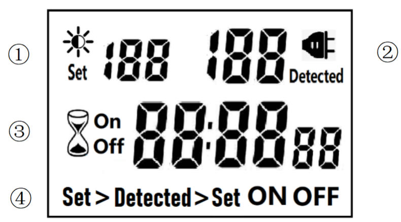
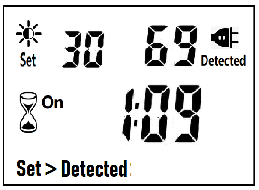
â‘ Light intensity setting
â‘¡ Light intensity detection
â‘¢ Countdown Timer ON & OFF
â‘£ 4 MODES:
Set > Detected: When the light intensity detection value is less than the set value, switch ON or OFF.
Detected > Set: When the light intensity detection value is greater than the set value, switch ON or OFF
ON : Always ON
OFF : Always OFF
NOTED:
1. The light intensity displayed by this machine is not the standard light intensity value (Lux), only the relative light intensity value.
2. The light intensity value is affected by the placement position and direction. Please determine the position first and then set it according to the actual light intensity detected. If you change the position or change the orientation, you need to reset the light intensity setting value suitable for the new position.
3. This product has built-in rechargeable battery. If it is not connected to AC for a long time, you need to connect the power supply to charge until the LCD can display normally.
MANUAL OPERATION
1. Press [UP" or [DOWN" to set the LUX value.
2. Press the [SET" key to start setting, and the P1 settable items will be flashed.
3. Press [UP" or [DOWN" to adjust the value.
4. Press [SET" key again to exit setting or enter next setting for countdown timer.
5. Repeat the [SET" key to start setting, and the P2 & P3 settable items will be flashed.


6. Press the [FUN" key to switch the working state in the following:
Set > Detected -> Detected > Set -> ON -> OFF
Set > Detected: Automatically switches when the detected ambient light intensity is darker than the set value
Detected >Set: Automatically switch when the detected ambient light intensity is brighter than the set value
When the brightness meets the setting conditions, the countdown starts as below:
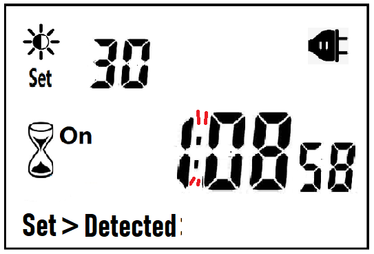
Note:when the countdown is ON, the detected value is not displayed.
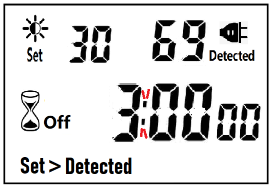
When the brightness does not meet the setting conditions, the countdown stops and waits:
After the countdown ON is reduced to 0, the countdown OFF starts immediately and the power is OFF.
After the countdown OFF is reduced to 0:
A. If the light intensity meets the set conditions, a new round of countdown will be started;
B. If the light intensity does not meet the set conditions, keep the power off and wait for the light to meet the conditions before turning on automatically.
NOTE:
1. If the power is cut off while the countdown is running, the countdown will be terminated immediately and the relay output will be off. After the power is turned on again, a new round of brightness detection will start.
2. Modifying the brightness value in the countdown operation will not affect the current countdown operation. After the off time of the current countdown, the new brightness setting value will take effect.
3. In the countdown on operation, change the setting value of the countdown on, this countdown will still be timed according to the original setting value; the new setting value will take effect when the next countdown on starts.
4. In the countdown off operation, change the setting value of countdown off, this countdown will still be timed according to the original setting value; the new setting value will take effect when the next countdown off is started.
NOTE: the brightness setting value, countdown ON or countdown OFF, any one of which is equal to 0, cannot be switched ON or OFF automatically.
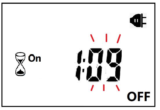
Manual Control
When ON or OFF is displayed, it means that the power supply remains ON or OFF, as shown in the figure below:

Power Detection and Standby Mode
With AC power supply, the icon ![]() lights up and works normally.
lights up and works normally.
When there is no AC power supply, the icon ![]() goes out, the brightness is not detected at this time, and the system enters the standby mode.
goes out, the brightness is not detected at this time, and the system enters the standby mode.
Photocell Timer, photocell timer socket, photocell sensor, photocell sensor socket, sensor plug, sensor switch socket, digital photocell timer, digital sensor timer
NINGBO COWELL ELECTRONICS & TECHNOLOGY CO., LTD , https://www.cowellsocket.com