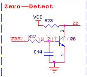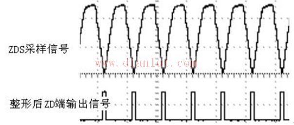

The zero-crossing detection circuit is shown in Figure 1. It is used to detect the zero-crossing point of AC220V, sample the full-wave rectified signal in the rectifier bridge, and form a shaping circuit through the triode and the resistor-capacitor to form a pulse wave, which can trigger an external interrupt. Zero detection. The sampling point and the shaped signal are shown in Figure 2.
Fiber Optic Patch Panel,Fiber Patch Panel,Fiber Distribution Panel,Optical Patch Panel
Cixi Dani Plastic Products Co.,Ltd , https://www.danifiberoptic.com
