This paper introduces a real-time control and data processing function using single-chip microcomputer, combined with the car's own speed detection and vibration sensing technology, to realize the car anti-collision and anti-theft alarm system. When the car continues to reversing more than two meters, it will issue an anti-collision alarm signal; when the car is locked, if the car body vibrates, an anti-theft alarm signal will be issued. At the same time, the alarm status as well as the alarm duration and number of alarms can be viewed from the LED display.
The basic principle of anti-theft vibration alarm
The burglar alarm system mainly uses a sensitive vibration sensor as a signal detecting device. The burglar alarm system automatically opens after the car is locked by default. It can also be forcibly closed by the anti-theft key switch after the lock is locked. The anti-theft detection is input by the magnetic shock sensor integrated circuit to the single-chip AT89C51. When the sensor detects the vibration, the output high level is received by the single-chip microcomputer through the inverter to perform anti-theft control, and the control transmitter sends an anti-theft signal (pulse). The driver receives the signal through the remote controller nearby, performs corresponding disposal, and cuts off at the same time. Start the circuit.
The specific working process is as follows: The anti-theft switch is connected to the P2.0 pin of the single-chip microcomputer. When the switch is closed, it enters the anti-theft state and delays for a period of time to ensure that the owner leaves and prevents false alarms. When the sensor detects vibration, it outputs a high level. After the inverter, the P1.6 end of the MCU is set to 0 to sound and light alarm, and the P1.7 end is set to 0 to cut off the startup circuit. At this time, the P1.4 end emits continuous. After the 50 kHz pulse is buffered, it is transmitted by the transmitter CZ27F, and is received by the remote controller for sound and light alarm.
The working process of the remote controller is as follows: the remote control has a built-in single-chip AT89C51. When the interrupt 0 receives the edge trigger signal, it enters the alarm program, and the P1 3 terminal of the single-chip microcomputer is set to 0 to perform the sound and light alarm. When it is detected that the closing switch is closed, the sound and light alarm is turned off; the P1.1 output pulse signal of the single chip microcomputer, the transmitter transmitting frequency signal is received by the alarm device in the car, and the remote control's own interrupt 0 is turned off to prevent false alarm. .
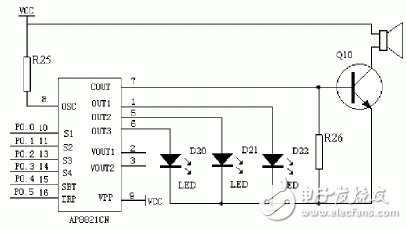
The schematic diagram of the sound and light alarm circuit is as follows:

Figure 2 sound and light alarm circuit
LED digital display circuit
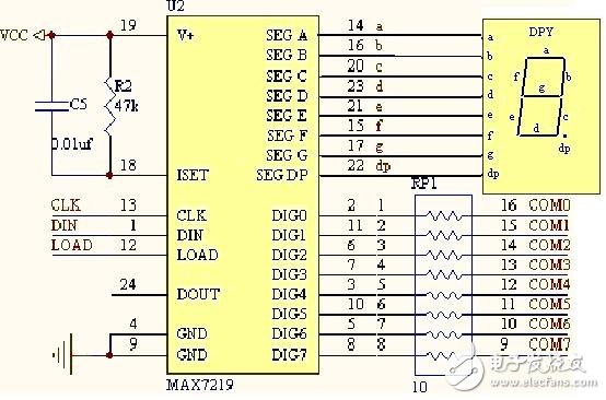
The output signal of the single chip microcomputer makes the LED digital display work normally under the cooperation of the driving circuit. The display circuit is one of the important functional circuits of the intelligent instrument. In order to simplify the circuit and reduce the cost, the dynamic display mode is usually adopted, and the Max7219 is used at a lower price. The MAX7219 of MAX is used to receive the data signal, and the voltage is raised by a resistor to eliminate the voltage, and finally the result is matched with the 7-segment LED display.
The schematic diagram of the display circuit is as follows:

8-bit digital display circuit based on MAX7219
The MAX7219 has a data latch function in which the stored signal LOAD and the input signal DIN are referenced by the clock signal CLK to transfer data on the active trigger edge.
cctv,cctv camera,outdoor,indoor,surveillance,home security
Dongguan Metalwork Technology Co., LTD. , https://www.diecast-pro.com
