Introduction to FPGA
Field Programmable Gate Array (FPGA) is a general-purpose user-programmable device first developed by Xilinx in the United States in 1984. FPGAs combine the high level of integration and versatility of gate array devices with the user-programmable flexibility of programmable logic devices.
The FPGA consists of a programmable logic cell array, routing resources, and an array of programmable I/O cells. An FPGA contains a wealth of logic gates, registers, and I/O resources. A single FPGA chip can implement a system implemented by hundreds or even more standard digital integrated circuits.
The FPGA is flexible in structure, and its logic cells, programmable interconnects, and I/O cells can be programmed by the user to implement any logic function to meet various design requirements. Its high speed, low power consumption and versatility make it ideal for complex system designs. Dynamic configuration and online system reconfiguration can be realized by using FPGA (the function of changing the circuit can be changed at different times when the system is running, so that the system has various spatially related or time-related tasks) and hardware softening and software hardening.
In view of the large scale and complicated function of the high-frequency fatigue testing machine controller, we have comprehensively upgraded the controller system through the combination of FPGA technology and microcomputer technology in the development process based on the traditional testing machine controller. The performance of the whole machine has improved the working efficiency, control precision and electrical system reliability, and the operation is convenient and the technological advancement is not lacking.
2 controller structure and content
The overall structure of the control system, the lower position machine is the core of the entire high-frequency fatigue test machine controller. It is used to realize the control signal and data of the control test machine, the processing of the feedback signal, and the data communication with the host computer. The strength of its control function also directly affects the performance of the entire controller. The waveform generator in the figure is used to excite and maintain the vibration of the electromagnetic exciter. Here, the waveform generator should output a sine wave.
3 Technical route taken by the system
Based on the realization of technical parameters and functional requirements, the system has adopted the following main technical routes in combination with current microelectronics technologies such as microcomputers and FPGAs:
(1) The lower computer is the core of system control. Because the control scale of the system is relatively complex, the control object has certain special characteristics (such as high frequency, high load, etc.), and involves controlling the motor, so instead of adopting the traditional 8-bit machine, the function is relatively more powerful and speed. Faster 16-bit machine - 87C196 series.
(2) The vibration exciter requires the input waveform to be a sine wave, and the frequency range of the test is 80 to 250 Hz. In addition, the system should also be able to perform sweep tests. In the sweep test, the system sweeps (roughly adjusts) in steps of 1 Hz, and then fine-tunes (in 0.1 Hz steps) on the basis of coarse adjustment to determine the resonance point of the system. It can be seen that a circuit module capable of generating a waveform with an accuracy of 0.1 Hz is a critical part of the overall system design and one of the design difficulties. This part cannot be or is difficult to achieve, such as by a microcontroller or other dedicated chip. The system uses FPGA as the waveform generator, as shown in the dotted line in Figure 1. The advantages of this are: high speed (general chip frequency is at least several tens of megahertz, even hundreds of megabytes) and can meet the above accuracy requirements; digital circuit implementation, good anti-interference; can integrate other logic circuits into the chip, Many discrete components are eliminated, while reducing the size; the waveform can be changed as needed.
(3) DC speed regulation is realized by variable voltage, and variable voltage is achieved by a controlled rectifier using a thyristor. The variable voltage is output to the phase shifting trigger through the single chip microcomputer, and the trigger output can control the conduction angle to the controllable rectifier to realize the adjustment of the motor speed. Helps improve the reliability of the system.
(4) Some important signals of the system are filtered by a digital filter, which is implemented by an FPGA. Compared with software filtering, this method is beneficial to improve the filtering effect of the signal, and the filtering speed is greatly improved.
4 partial module design
The FPGA part can be divided into two modules, in which the sine wave generator module can be subdivided into several small modules, as shown in Figure 2.
4.1 Latch design
The latch is used to stabilize the frequency data latch sent by the microcontroller in the FPGA and can be constructed with on-chip latch resources (or with flip-flops).
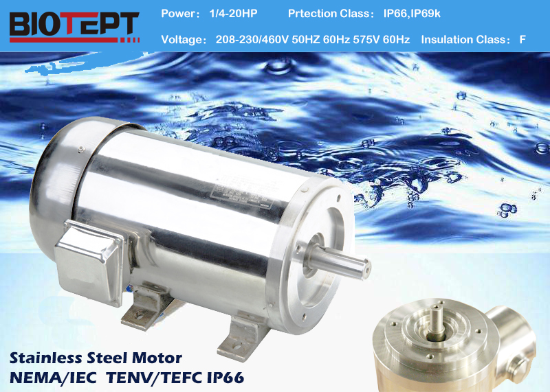
BIOTEPT NEMA and IEC Standard Stainless steel washdown AC motors have exterior components of 304 stainless steel to provide maximum corrosion resistance in severe-duty and washdown environments. The motors` exterior is completely paint- and coating-free and sealed against moisture and condensation to protect internal components.
Brands
DAYTON, LEESON, MARATHON MOTORS and U.S. MOTORS


Stainless Steel Motor,Washdown Duty Motors,Stainless Steel Ip69K Motors,Stainless Steel Washdown Nema Premium
Ningbo Biote Mechanical Electrical Co.,Ltd , https://www.biotept.com
