Abstract: Introduce the principle of using 51 series single-chip microcomputer to collect the infrared remote control signal of household appliances and forward it. The peripheral circuit of the infrared receiving chip and the procedure for measuring the received waveform are given in the article.
Infrared remote control is widely used in home appliances, but the remote controllers produced are not compatible with each other. At present, the common universal remote control on the market can only control certain types of products, it is not a real "universal", and it can not control the newly listed products. This article introduces a method for receiving and retransmitting infrared remote controller signals using a single-chip microcomputer. Because it only cares about the width of the high and low levels in the transmitted signal waveform, no matter how it is encoded, it can be used to implement a self-learning universal remote controller.
1. Infrared signal reception and waveform measurement
The output of all infrared remote controllers is generated by pulse amplitude modulation of the 38 to 40 kHz square wave with encoded serial data. If you directly measure the modulated wave, because the instruction cycle of the microcontroller is in the order of microseconds (μs), and the pulse width of the modulated wave is only more than 20 μs, a large error will occur. Therefore, demodulate the modulated wave and measure the demodulated waveform. 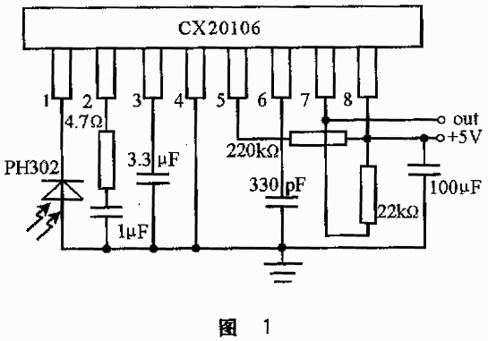
Infrared remote control receiving chip CX20106 can complete pre-amplification, limiting amplification, band-pass filtering, peak detection and waveform shaping of the remote control signal, and only need to add a simple peripheral circuit to complete the demodulation of the modulated wave, the principle is as follows Figure 1.
The remote control code pulse demodulated by CX20106 is directly connected to the INT0 and T0 pins of the 8751 microcontroller, the timer T) and T1 are initialized to the timer working mode 1, the GATE bit of T0. Each time the external interruption first stops the timing, records the count values ​​of T0 and T1, then clears the count values ​​of T0 and T1, and restarts the timing. The value of T0 is the high-level pulse width, and the value of T1-T0 is the low-level pulse width, as shown in Figure 2.
The flow of the external interrupt service routine for measuring waveforms is shown in Figure 3.
The external interrupt service routine for measuring waveforms is as follows:
interup0: clr tr0 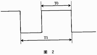
clr tr1
push psw
push acc
inc test
jb first, RE
mov a, tl0
mov temp1, a
mov a, th0
mov temp2, a
mov a, tl1
clr c 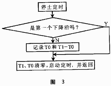
subb a, temp1
movx @ dptr, a
inc dptr
mov a, th1
subb a, temp2
movx @ dptr, a
inc dptr
mov a, temp1
movx @ dptr, a
inc dptr
mov a, temp2
movx @ dptr, a 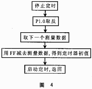
inc dptr
RE: clr first
mov tl0, # 0
mov th0, # 0
mov tl1, # 0
mov th1, # 0
setb tr0
setb tr1
Second, the forwarding of measurement data
Only need to use the data to periodically change P1.0 to get the original remote control code pulse, the process is shown in Figure 4.
3. Generate remote control transmission signal 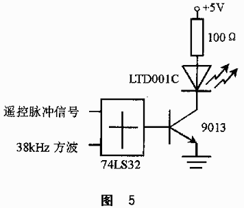
Use the remote control pulse signal to modulate the 38kHz square wave, and then amplify the modulated wave to drive the infrared light-emitting diode, you can get the remote emission signal. The modulation can be realized by an OR gate, and the 38kHz square wave can be generated by the timer T1 of 8755, as shown in Figure 5.
The carrier frequency of some remote controllers may be 40kHz, only need to slightly increase the transmission power can still use 38kHz carrier frequency to make its receiving circuit operate.
4. Application Field
You only need to add a keyboard and LCD or digital display circuit, and expand a certain amount of RAM, you can use this method to achieve self-learning universal remote control. The author has conducted experiments on common brands of color TVs, movie and butterfly machines, video recorders, projectors, air conditioners and other products currently on the market, and all have achieved accurate reception and forwarding. In addition, as long as a coding unit (available in software) is added in front of the circuit shown in Figure 5 as the transmitting unit; the circuit shown in Figure 1 plus the waveform measurement software as the receiving unit, plus the corresponding decoding control software can form a General infrared transceiver control system or data transmission system, no need to add additional hardware.
Lfp Battery,Lfp Battery Tesla,Lifepo4 Battery 12V 200Ah,Lifepo4 Battery 48V 100Ah
Langrui Energy (Shenzhen) Co.,Ltd , https://www.langruienergy.com
