Design principle : Â
In the future design, the development boards used will all be our own development boards. We use Cyclone4 series EP4CE10F17C8 for our chips . We will not discuss our development board in future designs.
Today's design is a water light. In the MCU, we also learned that the light of the water light is not bright or off at a high level or a low level, and then it turns on the LED light to form a running water.
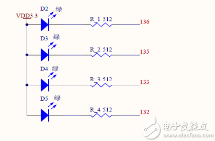
The circuit diagram of the development board we use is as follows
 Â
Â
In the dot diagram we can see that our lighting circuit, several lights are common is a high level that is 3.3V, so just give a low level can light our water lamp
The crystal oscillator provided by our development board is 50M, 50M one cycle is 20ns, our human eyes can distinguish the speed is about 45ms, that is, if the object moves once 45ms we see it is stopped for a while, if it is faster than At this time, then the movement of the objects we see is consistent. We need to design a flow that the human eye can distinguish, and we need to design a light that is greater than this time to go off, and then form a stream that the human eye can discern.
The flow time of our design water lamp is 1s. Then we need a time register. When the count reaches 1s, we light a lamp. When the next 1s comes, we light the next one, and then form a Flowing water, 50M is 20ns, 1s is 1hz, then we need to count 50,000,000.
It is worth mentioning that we count the time is an equation : count = crystal / frequency required, the count time is our 1hz period, then half the count is half a period, we can count in half Clk is flipped, then when the tech count reaches the 1hz period with 50% duty cycle
Â
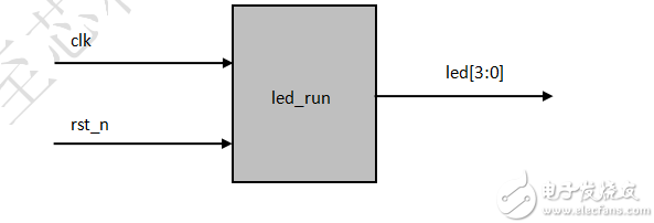
Design architecture diagram :

Design code :
Design module
0 Â Module led_run ( clk , rst_n , led );
1 Â
2 Â Input clk , rst_n ;
3 Â
4  Output  Reg  [ 3 : 0 ] led ;  Â
5 Â
6  Reg  [ 25 : 0 ] count ;
7 Â Reg clk_1hz ;
8 Â
9  Always  @  ( posedge clk )
10 if (! rst_n )
11 begin
12 clk_1hz <= Â 1 ;
13 count <= Â 0 ;
14 end
15 else  If ( count <  ( 50_000_000  /  1  /  2   -  1 ))  // count
16 count <= count + Â 1'd 1 ;
17 else
18 begin // When it counts up, get 1hz clock
19 count <= Â 26'd0 ;
20 clk_1hz <= Â ~ clk_1hz ; Â Â //~ clock flip
21 end
twenty two
23 always  @  ( posedge clk_1hz )
24 if (! rst_n )
25 led <= Â 4'b0111; // reset fourth lighting lamp, lamp 123 is off
26 else
27 led <= Â { led [ 0 ], led [ 3 : 1 ]}; Â Â // rising edge of the clock to the time when the led in the first place
Fourth 28 // 2 - 4 on 3 - 1 bits sequentially shift, i.e. a low level of the reset stop
29 // Move one of the 4 - 1 digits to achieve streamline
30 Â Endmodule Â
Â
Test module
0  `timescale  1ns / 1ps
1 Â
2 Â Module tb ();
3 Â
4 Â Reg clk , rst_n ; Â Â // Define the module's port
5  Wire  [ 3 : 0 ] led ;  Â
6 Â
7  Initial  Begin
8 Â
9 Â Clk = Â 1 ;
10 rst_n = Â 0 ;
11
12 # 200.1 rst_n = Â 1 ;
13
14 # 20000 Â $stop ; Â Â // Stop counting after delaying 20000 Ns
15
16 end
17
18 always  # 10 clk =  ~ clk ;   // Generate a 50M clock
19
20 led_run dut ( Â // Example design module
21 . clk ( clk ),
22 . rst_n ( rst_n ),
23. . led ( led )
24 );
25
26 Â Endmodule Â
Â
Simulation diagram :
In the simulation, we can adjust the count value in our design module so that we can wait for the simulation result in the simulation, otherwise you may not get the result after several hours of simulation.
  
In the simulation, we can see that on the rising edge of our 1hz clock, one of the 4 bits of our led will have a bit change to 0, thus realizing the flow of water.
Everyone can test under the board
The pin refers to the connection between the internal circuit of the integrated circuit (chip) and the peripheral circuit, and the pin constitutes the interface of the chip. According to the function, the pins of AT89S52 can be divided into four categories: main power supply, external crystal oscillator or oscillator, multi-function I/O port, and control, strobe and reset.
Terminal Pins,Terminal Hardware Pin,High Precision Terminal Pins,Terminal Pins For Pcb
Sichuan Xinlian electronic science and technology Company , https://www.sztmlchs.com
