
Â
Application:
The Outdoor Mounted  Bushing Current Transformer is self contained and designed to be mounted externally over the high voltage terminal bushing of 66kv to 500kv Power transformers, 66kv to 500kv Power circuit breakers and 66kv to 500kv Cable terminators .
In most cases the BCT, with its ease of installation, is a reliable and economical solution when upgrading system protection and adding additional metering points.
When properly installed, the  BCT can be used on higher system voltage levels while maintaining its own mere 600 Volt class rating. Its simple construction provides a low leakage product with virtually unlimited short circuit capabilities, far surpassing its stand alone wound-type counterpart
.
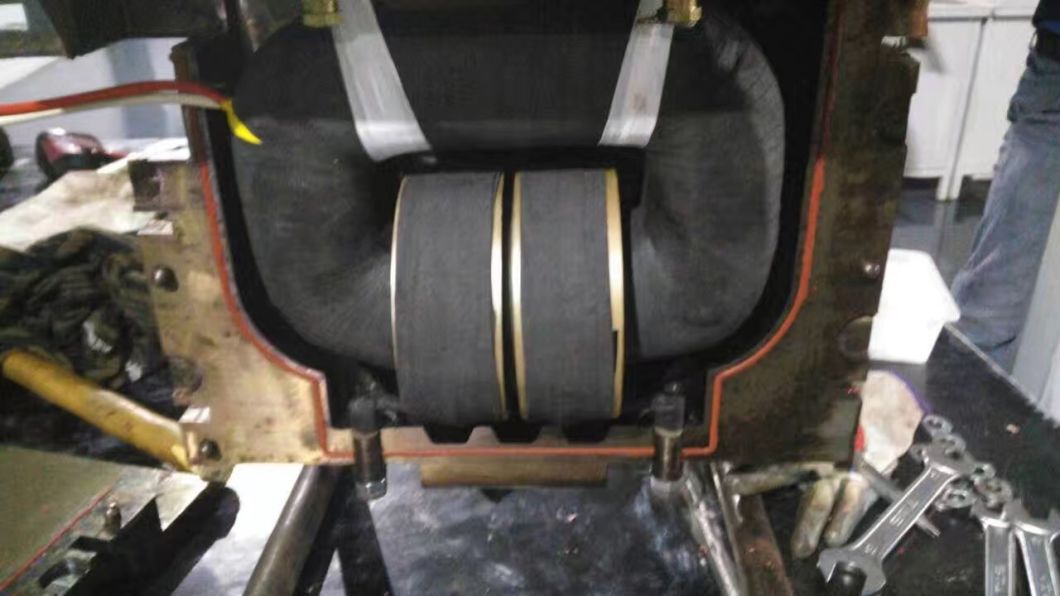
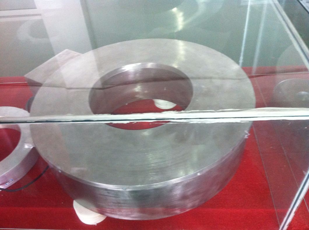
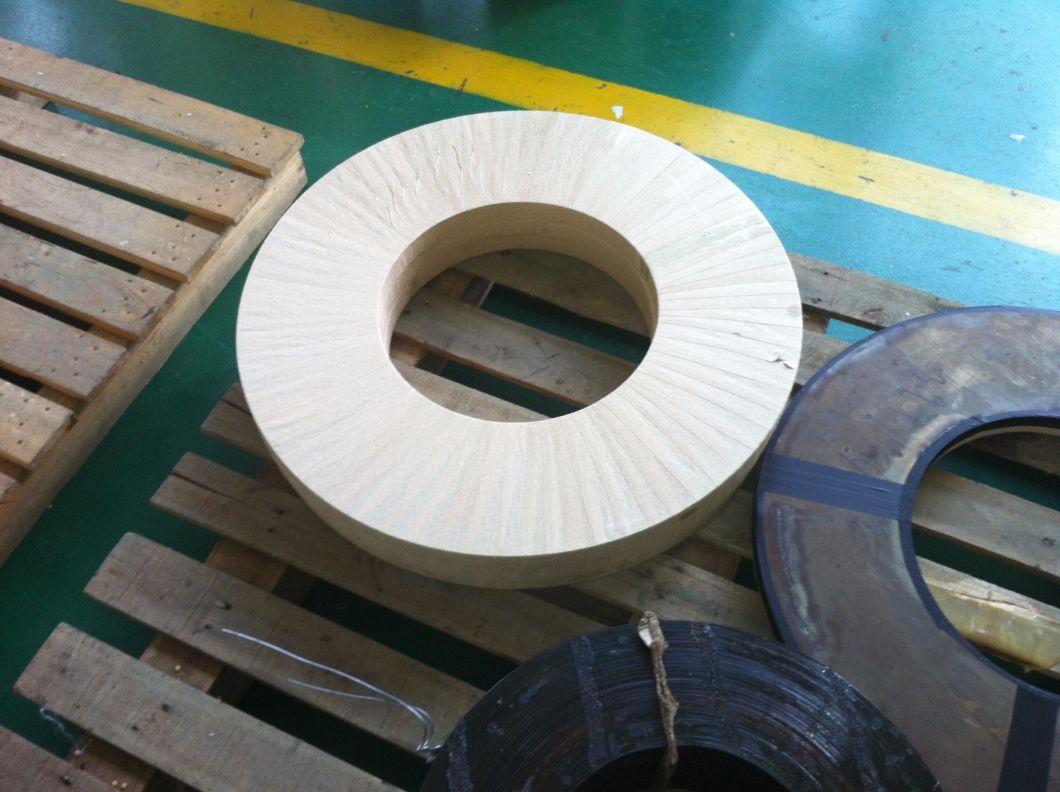
Construction:
The toroidal core is continuously tape wound using cold rolled grain oriented electrical grade silicon steel, which receives a full stress relief anneal after it is wound to its specified dimensions. The secondary winding is then wound of insulated copper magnet wire over the insulated core with the turns equally spaced around the core periphery. When taps are pulled, they are wound in a manner that assures a fully distributed winding between any connections. The coil is then fully encapsulated in an ANSI 70 (sky grey) resin system that has been developed and tested for outdoor use. The potting compound is U.V. stabilized, is flexible to allow for expansions caused by temperature variations from -50°C to +65°C, has good chemical resistance, high dielectric strength, rugged physical properties to endure mechanical shock, and overall excellent weather resistance.
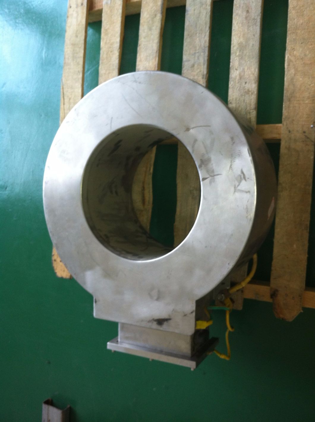
ÂInstallation:
ÂThe BCT is custom designed to fit over any bushing. It can be supported by mounting clamps with standard  bolt arm assembly & hardware for vertical adjustment. The placement of the bolts can be configured from either the ID or OD, and attached to the apparatus tank top. The number of clamps required is dependent on physical size and weight of the BCT. Custom mounting that permits attachment of clamping brackets directly to the bushing flange can also be provided - consult the factory for this option. In addition, a custom fitted ground shield may be installed on the top of the BCT and secured by the mounting clamps. This is highly recommended to direct any possible flash-over to the ground, thus bypassing the BCT preventing destruction of the BCT and connected equipment. Installation instructions are provided.
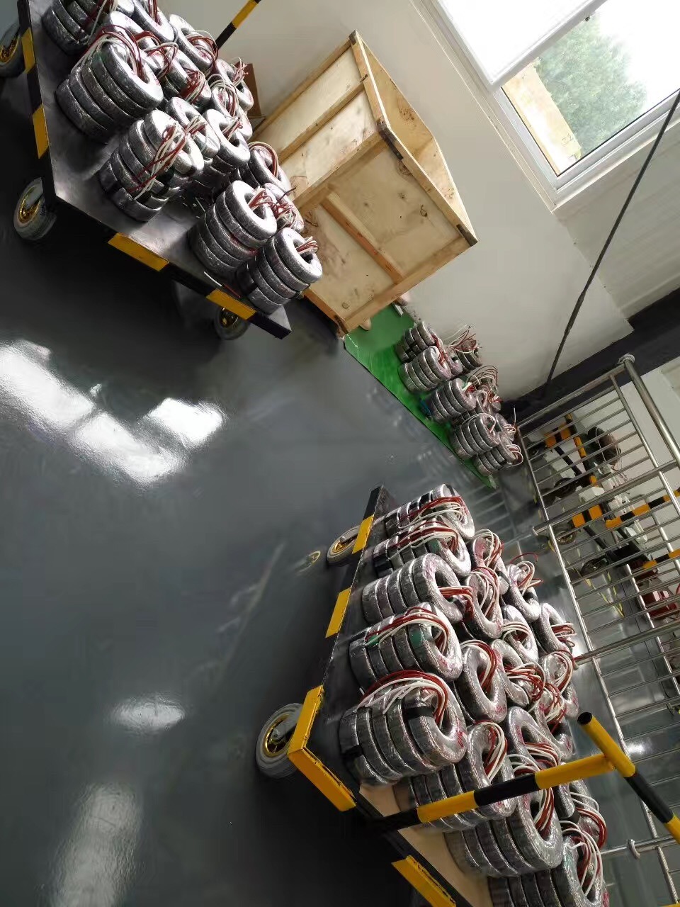
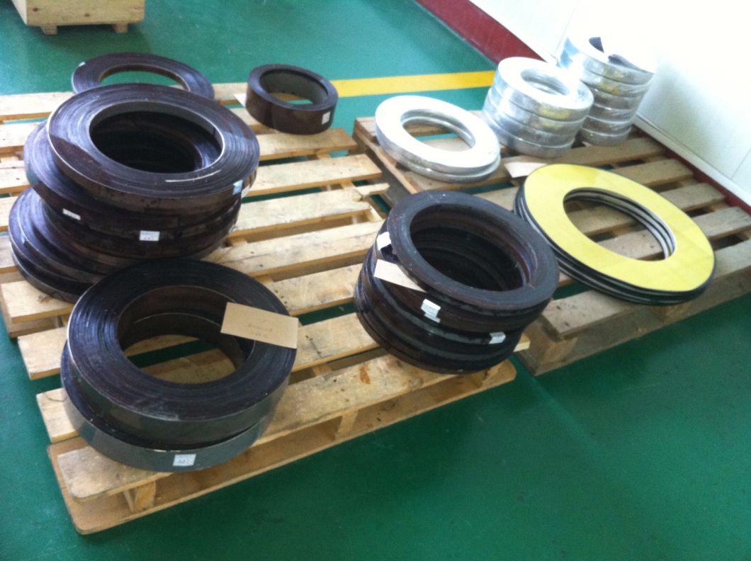
ÂHandling and Storage:
For domestic shipments, the BCT is usually palletized with spacers between the units and the pallet to allow for lifting. Ideally they should be lifted using endless slings in a 2-point or 3-point arrangement, lifting by fork lift or overhead hoist, one unit at a time. Caution should be employed while moving to avoid damaging or chipping the insulation, and, any sudden impacts to the unit or the conduit box. The units are outdoor rated so they may be left outside as originally packaged, but they should preferably be stored indoors until ready for use. Pallets should not be stacked.
ÂSize Selection:
Each unit is custom designed for its application. In addition to the current ratio, accuracy class and power frequency, some information regarding the equipment must be provided. Since there are countless configurations of equipment in the field, a site survey is recommended to aide with the proper sizing of the BCT. Often OEM outline drawings do not provide enough detail to determine this. We suggest submitting the original bushing drawing, digital photographs of each terminal and its immediate surroundings, and if possible some field measurements to locate potential obstacles such as conduit runs, oil gauges, manhole covers, lifting lugs, etc. Meramec Engineering will lay out the details using tools that will verify the size and strike clearances. Installation drawings will be provided for all custom mounted installations.
Overview of THE LVDS interface
LVDS, Low Voltage Differential Signaling, is a Low Differential signal technical interface. A digital video signal transmission method is developed to overcome the disadvantages of high power consumption and EMI electromagnetic interference when transmitting wideband high bit rate data in TTL level mode. The LVDS output interface USES a very low voltage swing (about 350mV) to transmit data through differential on two PCB routing lines or a pair of balanced cables, i.e. low-voltage differential signal transmission. LVDS output interface enables signals to be transmitted at a rate of several hundred Mbit/s on differential PCB lines or balanced cables. Low voltage and low current driving modes enable low noise and low power consumption.
Composition of THE LVDS interface circuit
In LCD, THE LVDS interface circuit consists of two parts: the LVDS output interface circuit on the motherboard side (LVDS transmitter) and the LVDS input interface circuit on the LCD panel side (LVDS receiver). The LVDS transmitter converts TTL signals into LVDS signals, and then sends the signals to THE LVDS decoder IC of LVDS receiver on the LCD panel side through a flexible cable (cable) between the driver panel and the LCD panel. The LVDS receiver then converts the serial signals into parallel SIGNALS of TTL level and sends them to the LCD panel timing control and the line and line drive circuit.
LVDS Cable,Vga Input Controller,Video Input Controller For Pvi Lcd,Vga Board For Pd064Vt8 Pd064Vt4,Vga Input Controller For Pvi Lcd
TONYA DISPLAY LIMITED , https://www.tydisplay.com