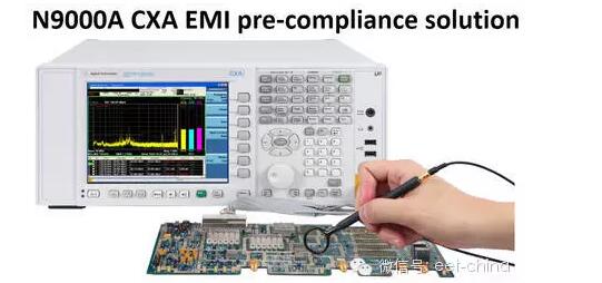
A spectrum analyzer is an instrument that studies the spectral structure of an electrical signal. It is used to measure signal distortion, modulation, spectral purity, frequency stability, and intermodulation distortion. It can be used to measure certain circuits such as amplifiers and filters. The parameter is a versatile electronic measuring instrument.
So how do you prevent damage to the spectrum analyzer? Let's learn along with Antai maintenance Chinese workers:

1. Always use the three-phase AC power cord that comes with the analyzer.
2. Ground the instrument correctly to prevent static charge accumulation. The accumulation of a large amount of static charge may cause damage to the instrument and personal injury to the operator.
3. Do not use extension cables, power cables or autotransformers without unprotected grounding conductors to avoid damage to grounding protection.
4. Check the quality and polarity of the AC power supply; typically the required AC voltage is 100 V, 120 V, 220 V ±10% or 240 V + 5%/-10%. The expected ground wire resistance is < 1 Ω, the voltage between the neutral and ground lines is <1V, and an uninterruptible power supply [UPS] is installed if necessary.
1. Do not exceed the value of the parameter provided in the Technical Indicators Guide or the value indicated on the yellow warning label on the Analyzer.
2. Please refer to the Technical Indicators Guide for the conditions required to achieve the listed technical indicators. Please note the information on settling time, instrument settings and calibration requirements.
3. For example, the yellow warning label on the front panel of the E4440A PSA indicates that the maximum RF input power is 30 dBm (1W) and 0 Vdc DC-coupled voltage or 100Vdc AC-coupled voltage.
1. Limit the signal level that will be measured using the spectrum analyzer to avoid front-end damage. Applying excessive power to the front end can cause damage to the front end components. The typical maximum RF input signal level is 30dBm (1W).
2. Turn off the DUT/source or reduce the power of the DUT/source before turning on or off the connected device or device under test. This helps prevent accidental voltage rises or falls and avoids affecting the analyzer's input or output. Use DC blockers, limiters or external attenuators as needed.
For example, the 1Keysight 11867A RF Limiter provides input protection. It will reflect signals with an average power of up to 10 W and peak power of up to 100 W. In many spectrum analyzer applications, the 11867A provides input protection for attenuators and mixers to a specified frequency range.
The 211742A DC blocking capacitor blocks DC signals below 45 MHz, allowing signals up to 26.5 GHz to pass. It is suitable for use with high frequency oscilloscopes or in biased microwave circuits to suppress low frequency signals that can damage expensive measuring instruments.
1. Be careful not to bend, impact or fold any DUT connected to the input of the analyzer, such as filters, attenuators or long cables. This reduces the tension on the input connectors and installed hardware.
2. Ensure that the input supports the external connection device properly (rather than hanging it).
3. Do not mix 50Ω and 75Ω connectors and cables.
1. Avoid bending the cable repeatedly. Excessive bending angles can damage the cable immediately.
2. Limit the number of connections and disconnections to reduce wear.
3. Check before using the connector; Checking for connectors with dirt, cracks, and other signs of damage or wear may cause problems with the intact connector.
4. Always use a torque wrench and gauge tool to connect the RF connector.
5. Clean the dirt-contaminated connector to avoid damage to the electrical properties of the connection or damage to the connection.
1. Electrostatic discharge (ESD) can damage or damage electronic components. Therefore, try to test on the anti-static station. Leave all components at least 1 meter away from materials that may generate static electricity. Immediately short the center of the cable and the outer conductor together to ground the coaxial cable before connecting it to the analyzer.
2. Install ESD hoods on all RF connectors before transporting and moving equipment.
1. Regularly inspect and clean the vents of the instrument. Poor air circulation can cause the instrument to operate at too high a temperature and cause a malfunction. The optimum operating temperature of the instrument is 20 ° C to 30 ° C.
2. When installing the product in the chassis, the air convection passage into and out of the instrument must not be obstructed. For every 100 W of power consumed by the chassis, the ambient temperature must be 4 °C below the maximum operating temperature of the product. If the total power consumption of the chassis is greater than 800 W, forced ventilation must be used.
1. When transporting the instrument, hold the instrument handle and lift the instrument.
2. Avoid lifting the instrument directly by grasping the front panel with your hand. If the instrument slips off, it may damage the keyboard, knob, or input connector.
3. Use a small cart or use two people to help move heavy instruments. Pack the instrument correctly for transport.
4. The use of non-designated packaging materials may cause damage to the instrument. Do not use styrene beads of any shape as packaging materials. They do not provide sufficient cushioning for the device and may generate static electricity and cause damage to the device. Try to keep the original packaging as you reuse it when transporting the instrument.
1. Before making any measurements, first check the measurement procedures and settings required for the particular application (see Measurement Guide).
2. Depending on the type of repair, the analyzer settings must be restored to factory settings.
Portable Battery ,Portable Power Bank,Portable Battery Pack,Portable Power Pack
Zhejiang Casnovo Materials Co., Ltd. , https://www.casnovo-new-energy.com
