
High frequency resistance
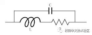
The most common circuit component in low-frequency electronics is the resistor. Its role is to reduce the voltage by packing some electrical energy into heat energy. The high-frequency equivalent circuit of the resistor is shown in the figure, in which two inductors L simulate the parasitic inductance of the leads at both ends of the resistor, and at the same time, the capacitance effect must be taken into account according to the structure of the actual lead; the capacitor C is used to simulate the charge separation effect.
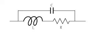
Resistance equivalent circuit representation
According to the equivalent circuit diagram of the resistor, the impedance of the entire resistor can be easily calculated:
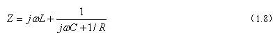
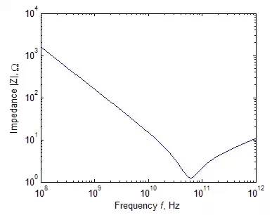
The figure below shows the absolute value of the impedance of the resistor as a function of frequency. As you can see, the impedance of the resistor at low frequencies is R. However, when the frequency rises above a certain value, the effect of parasitic capacitance becomes dominant, causing Resistance resistance drops. As the frequency continues to increase, the total impedance rises due to lead inductance, and the lead inductance represents an open or infinite impedance at very high frequencies.
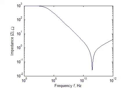
A Typical 1KΩ Resistance Impedance Absolute vs. Frequency
High frequency capacitance
Chip capacitors are widely used in RF circuits. They can be used in many circuits such as filter frequency modulation, matching networks, and transistor bias. It is therefore necessary to understand their high frequency characteristics. The high-frequency equivalent circuit of the capacitor is shown in the figure, where L is the parasitic inductance of the lead; the lead conductor loss is described by a series equivalent resistor R1; the dielectric loss is described by a parallel resistor R2.
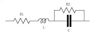
Capacitance equivalent circuit representation
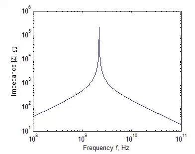
The relationship between the absolute value of the impedance of a typical capacitor and the frequency can also be obtained. As shown in the figure below, the capacitor exhibits the same resonant characteristics as the resistor due to dielectric loss and finite length leads.
A typical 1pF capacitor impedance absolute value vs. frequency
High frequency inductance
The use of inductors is relatively small with respect to resistors and capacitors. It is mainly used in transistor bias networks or filters. Inductors are usually formed by winding the conductors on a round conductor post. Therefore, in addition to considering its own inductive characteristics, the inductance also needs to consider the resistance of the wire and the distributed capacitance between adjacent coils. The equivalent circuit model of the inductor is shown in the figure below. The parasitic bypass capacitor C and the series resistor R have the combined effects of distributed capacitance and resistance.
High-frequency inductor equivalent circuit
As with the resistors and capacitors, the high-frequency characteristics of the inductor are also different from the expected characteristics of the ideal inductor, as shown in the figure below: First, when the frequency is close to the resonance point, the impedance of the high-frequency inductor increases rapidly; second, when the frequency continues to increase The influence of the parasitic capacitance C becomes dominant, and the coil impedance gradually decreases.
Inductor Impedance Absolute Value vs. Frequency
In short, in high-frequency circuits, the performance of the basic passive components such as wires, basic resistors, capacitors, and inductors is clearly different from that of ideal components. The reader can find a constant resistance value at low frequencies, which corresponds to a second-order system with resonance points at high frequencies. At high frequencies, the dielectric in the capacitor is depleted, causing the impedance characteristics of the capacitor to appear only at low frequencies. The frequency is inversely proportional; at low frequencies, the impedance response of the inductor increases linearly as the frequency increases, deviating from the ideal characteristic before reaching the resonance point, and eventually becoming capacitive. The characteristics of these passive components at high frequencies can be described by the aforementioned quality factor. For capacitors and inductors, the highest possible quality factor is usually desired for tuning purposes.
DADNCELL 1.5V AAA alkaline batteries are more suitable for long-lasting continuous discharge and high-performance power consumption equipment because of their unique internal component structure, coupled with better battery materials, improved power capacity and electrical performance, and the same model of DADNCELL 1.5V AAA alkaline cell capacity and discharge time, Alkaline battery capacity and discharge time are 4-7 times that of ordinary batteries, and the gap in power discharge performance at high and low temperature is even wider.
At present, all types of cells developed by DADNCELL Labs do not involve any heavy metals in production, are green and can be disposed of with domestic waste.
DADNCELL 1.5V AAA battery advocates a more comfortable and smooth power supply experience for household appliances. Alkaline zinc-manganese dry battery series is suitable for various common household electronic equipment instruments such as smart door locks, infrared thermometers, cameras, flash lights, razors, electric toys, instruments, high-power remote controls, Bluetooth wireless mouse keyboards, etc.
1.5V Lr6 Alkaline Batteries,1.5V Lr6 Batteries For Bluetooth Wireless Mouse,Aa 1.5V Batteries For Electric Toys,Lr6 Suitable For High-Power Remote Control
Shandong Huachuang Times Optoelectronics Technology Co., Ltd. , https://www.dadncell.com