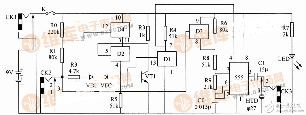
As shown in the figure, it is a multi-purpose logic pen circuit diagram composed of four bidirectional analog switches CD4066D1~D4) and 555 time base circuit, which can realize three-state audio logic pen, acoustic signal proofreader, audio signal generator and 555 time base circuit. Five functions of the monitor and the door whistle.

Multipurpose logic pen circuit
In the figure, D2, D4 and R5 form two input and gates, and D1 and R3, R4 and VT1 constitute a NOT gate. The 555 circuit forms a multivibrator with R8, R9, R6, C0, etc., and the be junction of VD1, VD2 and VT1 forms a reference level when measuring the logic level of the external circuit.
This circuit can realize five functions.
(1) Three-state audio logic pen. Insert the plug with the double lead into CK2 and CK3 as the positive and negative poles of the logic pen. When measuring, when the treble is emitted, it indicates high level; when the bass is emitted, it indicates low level; when no sound is emitted, it indicates that it is not connected.
When the positive probe is connected to the high level and the negative probe is connected to the circuit under test, the VT1 oscillation frequency is:

(2) Acoustic signal proofreader. Short the short pins.
(3) Audio signal generator. The audio signal is output by CK3.
(4) 555 time base circuit detector.
(5) When using a speaker instead of a piezoelectric buzzer, it can be used as a door whistle.
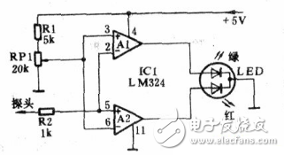
Three-lamp logic pen circuit production (2)This article describes a simple logic pen (also known as logic level tester) circuit. This logic pen circuit (see figure) can be used to accurately detect the level of digital signals in the remote control system and the presence or absence of pulse signals. IC1 uses two comparators in the quad voltage comparison integrated circuit LM324. The non-inverting input and the inverting input of Al and A2 are connected to each other and connected to two sets of inputs. A set of voltage dividing circuits composed of R1 and RP1 is used as a threshold reference voltage input terminal. Adjust potentiometer RP1 to vary the threshold voltage from 0V to 4/5vDD to accommodate the selection and testing of logic levels such as DTI_, TTL or CMOS. The other set of inputs is coupled to the measured points via R2. According to the working principle of the voltage comparator, when the potential of the non-inverting input terminal is higher than the potential of the inverting input terminal, the comparator outputs a high level, and vice versa, when the potential of the non-inverting input terminal is lower than the potential of the inverting input terminal, the output of the specific converter is output. Low level. If the measured level is high (compared with the threshold voltage set by RP1), the potential of the 2 pin of Al is higher than 3, the output of 1 pin is low, and the green tube in the LED of the composite LED is not turned off. At the same time, the 5 pin potential of A2 is higher than 6 feet, the 7 pin output is high level, and the red light tube is turned on. Similarly, if the measured point is low level, the 1 pin outputs a high level, the 7 pin outputs a low level, the green light tube illuminates, and the red light emitting tube is turned off. If the input is a pulse signal, Al and A2 alternately output a high level or a low level. When the pulse frequency is low, the red and green light-emitting tubes can be seen to alternately flash; when the frequency is high, the light-emitting tube is orange-red, indicating that the measured point has a pulse signal.

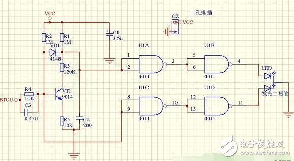
Circuit diagram The two LEDs here are actually a three-pin two-color diode pcb packaged with a 3pin connector instead. At the time, the schematic diagram was mainly for drawing the main emphasis on the electrical connection of the pcb, so it does not look very beautiful, forgive me. .

PCB layout

3D simulation view

Toggle switches
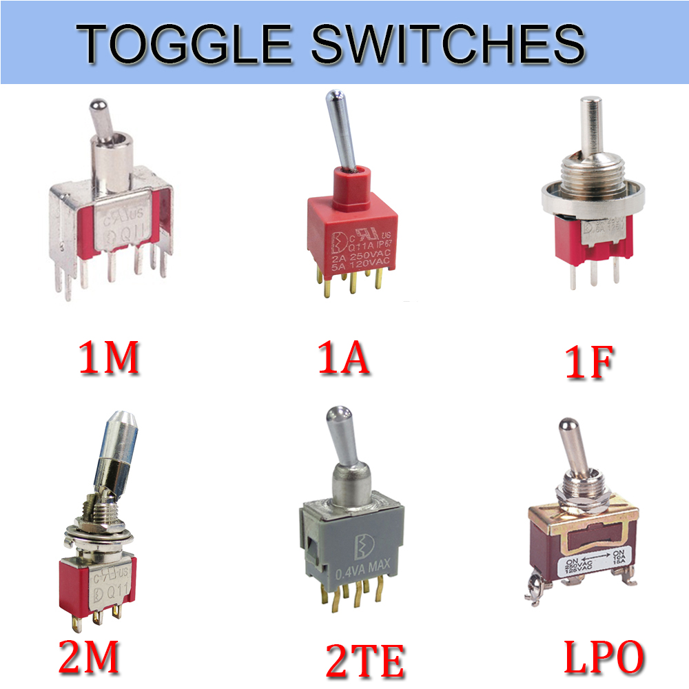
Toggle switches, also called On Off Toggle Switches, is often used as the switching device of the equipment stalls. Meanwhile, we are also offer our customers Key Switches, Metal Switches, Automotive Switches, Push Button Switches, etc.
The Electrical Toggle Switches is a manually controlled Toggle Switches similar to the dial switch. Most of this Latching Toggle Switches are widely used in on-off control of AC and DC power circuits, and are less commonly used in circuits of several kilohertz or up to 1 megahertz. Let's take a look at the following.

1. Splash-proof knob button switch
The panel is installed with a splash-proof `O` ring seal, and the knob is a ball. It is a splash-proof ball button knob switch. Its terminals are in a straight line and the bottom of the terminals is sealed with epoxy resin. Strong corrosion resistance, suitable for automotive parts
2. Vertical Mount Right Angle Toggle Switch
The vertical mounting of the terminals and the terminal pins are right-angled, so it is a vertically mounted right-angled toggle switch. Its contacts are gold-plated and highly reliable. Mostly used in anti-theft devices, alert system.
3. Bipolar single toggle switch
At the same time, the switch breaks the phase line and the N line and controls one branch. Therefore, it is a bipolar single toggle switches. The contacts are in 3PDT form and are used for multimedia speakers and stereos.
4. Standard surface mount unthreaded toggle switches
The terminal adopts the standard mounting mode. Its sleeve has no thread. It is called a standard surface mount screw-less switch. The contacts are SPDT and its electrical life is as high as 55,000. Used for medical equipment
5. Horizontally mounted right-angle toggle switch
Compared to the vertical switch, it only changes direction to horizontal, so it is horizontally mounted right-angle toggle switch. The contacts are double-pole double-throw and the bottom of the terminal is Epoxy Seal. Mostly used for computer peripherals.

Toggle Switches,Toggle Switch On Off,Toggle Switch Autozone,Toggle Switch Home Depot
YESWITCH ELECTRONICS CO., LTD. , https://www.yeswitches.com
