The buck converter has a wide range of applications in electronic equipment and is a core part of modern power electronic systems. Its operating state directly affects the performance of the entire power electronic system. The use of a linear regulator through the buck will inevitably lead to a problem of low power conversion efficiency. The buck converter (BuCk), also known as a series switching regulator or a switching buck regulator, can provide the required low voltage. Power supply, constant current, and high conversion efficiency.
1, Buck converter overview
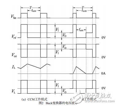
The Buck converter is also called a buck converter. As shown in the model circuit of the Buck converter, the switching transistor VT is controlled by PWM. When VT is on (the conduction voltage drop is zero), the voltage applied to the inductor L is (Vi−V0). Since the voltage across the inductor is constant, the current of the inductor rises linearly with a slope of dIL/dt=( VI−V)/L, which causes the inductor's current IL to be a stepped ramp, as shown in Figure 2(a). At this time, the inductor voltage is left and right negative, the diode VD is turned off due to the back pressure, and the power supply charges the capacitor C0 and supplies power to the load.
When the VT is turned off, the inductor current cannot be abruptly changed, the voltage is reversed to the left and the right is positive, and the VD is turned on, and the voltage at the left end of the inductor L is clamped to a diode lowering voltage drop (about 1 V) lower than the ground. At this point, the current flowing through VT now shifts to the flow direction VD, as shown in Figure 2(a). The slope is dIL/dt=(Vo+1)/L, the inductor current decreases linearly, and the capacitor C0 discharges. Power the load.

The operating waveform of the Buck converter is shown in Figure 2. In Fig. 2(a), when the switching transistor VT and the diode VD are respectively turned off, the reverse voltage Vrd of Vce and VD of the VT is Vi. During ton, the inductor L is excited by the voltage (Vi−V0), stores energy, and the magnetic flux increases. During the toff period, the output voltage V0 is opposite to the direction when the switch is turned on, and is added to the inductor L to demagnetize and release energy, and the magnetic flux is reduced. According to the "Volt-second equal principle", the following equation is established.
(VI-VO) & TImes; ton=VO&TImes;tOFF
Considering toff=T-ton, the above formula can be converted into
V0=ton*Vi/T=D*Vi(1)
(a) CCM working mode (b) DCM working mode diagram
2, the voltage waveform of the Buck converterSince the inductor current IL never drops to zero throughout the cycle, this mode of operation is called CCM mode. In this state, if the inductance of the inductor is reduced or the load is reduced, the DCM mode in which the inductor current drops to zero as shown in Fig. 2(b) will occur under certain conditions.

12 Inch Woofer,12Inch Speaker,12 Inch Audio Parts Speaker,Neodymium Speaker
Guangzhou BMY Electronic Limited company , https://www.bmy-speakers.com
