Secondary circuit Definition: All low-voltage circuits such as measurement circuit, relay protection circuit, switch control and signal circuit, operating power circuit, circuit breaker and electrical lockout circuit of isolation switch. An electrical circuit that is connected to each other by a secondary device to form a monitoring, control, regulation, and protection of the primary device is called a secondary circuit. It is a circuit that is connected in the electrical system by a secondary winding of a transformer, a measurement monitoring instrument, a relay, an automatic device, etc. through a control cable. It is used to control, protect, regulate, measure and monitor the working conditions of various parameters and components in the primary circuit. The circuits used to monitor the electrical connections formed by the meter, the control signal, the relay protection, and the automatic device are referred to as secondary circuits or secondary wires.
Detailed secondary circuit
5, according to Figure 5 with a spring energy storage operating mechanism circuit breaker control, signal circuit diagram to illustrate the name of each component, the process of action
Answer: Figure 5 shows the circuit breaker control and signal circuit of SW4-110 type circuit breaker with spring operating mechanism. There is a spring in the closing coil of the circuit breaker. The energy storage latching contact SQS1 can only be closed after the spring energy storage; With automatic reclosing, if it is coincident with permanent failure, the spring can't reach the energy storage (requires 9S), so it can't overlap for the second time. For the sake of reliability, an "anti-jump" loop has been added.
When the KAC is activated by the KQT of the trip position relay, one end of the KQT coil should be connected between SQS and QF. If the wiring is in the past, before the SQS, when the KAC is activated and overlaps with the permanent fault, the spring energy storage is released, the SQS is opened, the KQT is de-energized, the KAC starting circuit is disconnected, and the capacitance in the reclosing relay is re-established. When the charge is sufficient, after the spring is re-storage, the SQS is closed, the KQT coil is energized, the KAC is activated, and a reclosing is performed. In this case, if the control switch is not opened in time, it will be repeated several times.
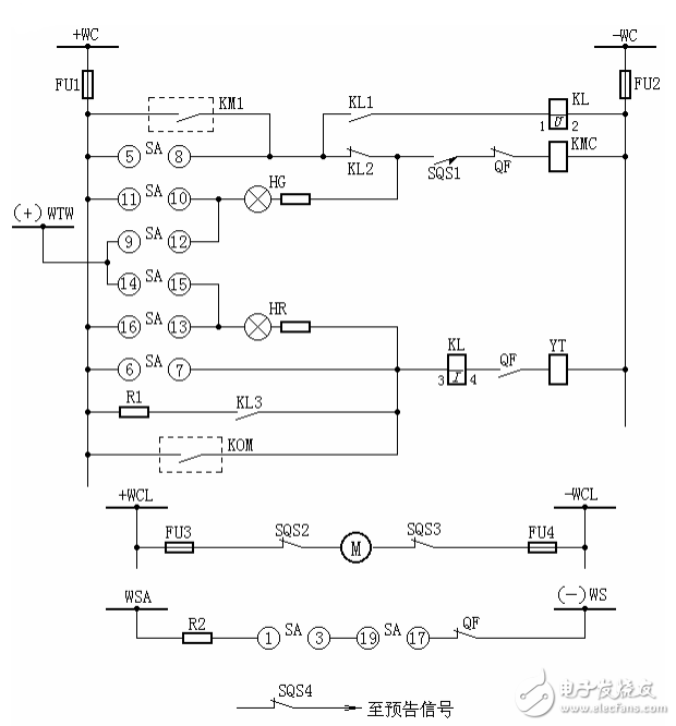
Figure 5 Circuit breaker control and signal loop wiring diagram of spring operating mechanism
6, according to Figure 6 with a hydraulic operating mechanism circuit breaker control, signal circuit diagram to illustrate the name of each component, the process of action
Answer: The working pressure of the hydraulic mechanism is different from each manufacturer. Take the CY3 type produced by Beijing Switch Factory as an example. At 20 °C, the rated air reservoir pressure is 11.7±0.98MPa, the rated pressure is 17.65MPa, when the temperature changes by 1°C. The pre-charge pressure changes by 0.045 MPa.
In Figure 6, when the hydraulic pressure is lower than 14.72 MPa, the pressure contact SP4 in the closing circuit is disconnected, and the closing is not allowed; when the hydraulic pressure is lower than 13.73 MPa, the pressure contact SP5 in the trip circuit is disconnected, and tripping is not allowed. If the grid operation allows, it can also be used to trip after the intermediate relay is activated by this contact.
When the pressure is lower than 15.72 MPa, the 3SP3 contact is closed, and the oil pressure reduction signal is issued; when the hydraulic pressure is lower than 16.72 MPa, the contacts SP1 and SP2 are closed, and the oil pump is started to be pressed. When the oil pressure rises to 18.63 MPa, SP1 and SP2 are both. Disconnected, the oil pump stops pressing. When the pressure is lower than 9.8MPa or higher than 24.5, MPa, the pressure abnormality signal is issued by the contact PP1 and PP2 of the pressure gauge, and the KM3 normally closed contact can be used to lock the start circuit of the contactor of the oil pump motor (in the figure) Not shown), preventing the oil pump from starting may cause a slow-distribution of the circuit breaker when the oil pressure drops to zero.
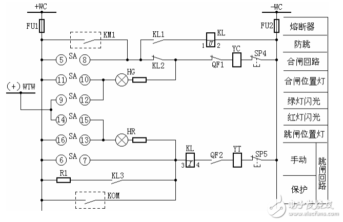
Figure 6 Circuit breaker control and signal loop wiring diagram of hydraulic mechanism
7. According to Figure 7, the wiring diagram of the flash device consisting of two intermediate relays, illustrating the action process
A: The principle wiring of the flash unit consisting of two intermediate relays is shown in Figure 7. When the position of a certain circuit breaker does not correspond to its control switch, the flash bus (+) WTW passes through the "non-corresponding" circuit, the signal light (HR or HG) and the operating coil (YT or YC) are connected to the negative power source, and KM1 is activated. KM1 normally open contact is closed, KM2 is started one after another, its normally open contact shorts the KM1 coil, and the flash bus is directly communicated with the normal power supply, the signal light (HR or HG) is fully illuminated; when the KM1 contact is delayed KM2 loses magnetism, its normally open contact is open, the normally closed contact is closed, KM1 is started again, the flash bus (+) WTW is connected to the positive power supply via the KM1 coil, and the signal light in the "not corresponding" circuit is semi-bright. Repeat the above process to send a continuous flash signal. The KM1 and KM2 have a time-delay reset to make the flash more visible.
In the figure, the signal light HW of the test button SE is used for the simulation test. When the SE is depressed, the flash bus (+) WTW is turned on by the signal light HW and the negative power source, and the flash device operates in the above-described order to cause the test lamp HW to emit a flash signal. The normally closed contact of the HW via the button is connected between the positive and negative power supplies, and thus doubles as the monitor light for the flash device fuse.
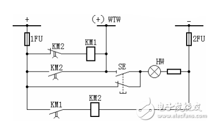
Figure 7 Wiring diagram of the flash unit consisting of two intermediate relays
8. Explain the name and operation process of each symbol component according to Figure 8.
A: Commonly used central resetting can be used to repeat the action signal device. The so-called accident signal that the central reset can be repeated is that after the circuit breaker is automatically tripped, in order to prevent the on-duty personnel from being interfered with by the long-term interference of the acoustic signal, the green light flash signal can be retained and the acoustic signal can be immediately released.
In Figure 8, KSP1 is the ZC-23 type impulse relay. The diode V and capacitor C connected in parallel on the primary side of the pulse converter T have anti-interference effect; the diode V in parallel on the secondary side acts to suddenly reduce the primary current of T. The current bypass induced on the secondary side makes the reed relay KR not malfunction (because the reed relay does not have directionality). The principle is that when the circuit breaker accident is opened or the test button SE1 is pressed, the current transformer has a current increase in the primary winding, the induced current in the secondary winding starts KR, and the intermediate relay KM is activated after the KR action. KM has two pairs of contacts, one pair of contacts closes to start the buzzer HB, and emits an audible signal; the other pair of contacts closes the start time relay KT1, after a certain delay, KT1 starts KM1, KM1 moves, so that KM loses The magnetic return, so the sound stops, and the entire accident signal loop returns to the original state.
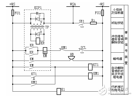
Figure 8 Circuit diagram of the accident signal device loop formed by ZC-23 type impact relay
When the second circuit breaker is tripped, the sound is emitted, and the starting circuit is not corresponding to Figure 9. In Fig. 8, the normally open contact KM2 is derived from the warning signal device, so the time relay KT1 and the intermediate relay KM1 for automatically releasing the sound are shared by the two sets of acoustic signal devices.
In order to test the integrity of the accidental sound device, a test button SE1 is also provided. When SE1 is pressed, the KSP1 can be activated to make the device sound and return to the original state according to the above procedure.
The audio signal can also be released by pressing the manual reset button.
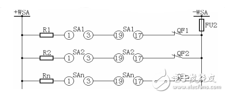
Figure 9
Over time, battery cables have to be replaced due to corrosion or damage. A bad battery cable can cause intermittent starting issues or lack of power to the vehicle, including arcing or power drains.A battery cable consists of multiple stands of wire encased in synthetic material with different types of battery terminals on each end for a reliable connection. Corrosion is the number one cause of battery cable failure, stopping the flow of electricity.
Battery cable, power cable, battery cable assembly, battery wiring
ETOP WIREHARNESS LIMITED , https://www.wireharnessetop.com
