[Introduction] This article mainly talks about the 3V-5V level conversion circuit diagram, let's learn together.
Keywords: level-shifting triode This article mainly talks about the 3V-5V level-shifting circuit diagram. Let's take a look at it:
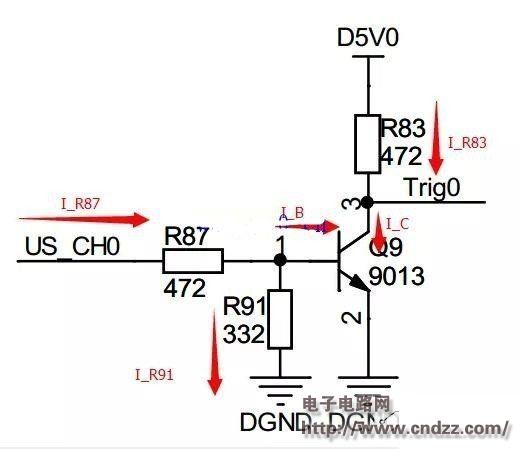
The left end of the figure is connected to the 3.3V CMOS level, which can be an IO port of STM32, FPGA, etc., and the output of the right end is 5V level, achieving conversion from 3.3V to 5V.
Now let's analyze the role of each resistor (the core idea of ​​grabbing is that the Vbe of the triode is constant at around 0.7V):
Assuming no R87, when the high level of US_CH0 is directly added to the BE of the triode, where is the voltage of 0.7V going?
Suppose there is no R91. When the state of US_CH0 is uncertain, the default is to output high or low level of Trig? Therefore, R91 functions as a fixed level. At the same time, if there is no R91, just turn on the triode by inputting “0.7Vâ€, the threshold voltage is too low, and R91 has the function of raising the threshold voltage (refer to the second section for the analysis of the buzzer).
3V-5V level conversion circuit diagram

However, if you add R91, you should pay attention to it: if R91 is too small, the base voltage is only about Vb"0.7V, so that US_CH0 can be turned on when it is high. Vb=1.36V in the above figure.
Suppose there is no R83. When the input US_CH0 is high (when the transistor is turned on), D5V0 (5V high level) is directly added to the CE level of the triode, and the CE and triode of the triode are easily damaged.
Further analysis of its working mechanism:
When the input is high, the transistor is turned on, and the output is clamped to the Vce of the triode. The test result for the circuit is only 0.1V.
When the input is low, the transistor is not conducting, and the output is equivalent to pulling up the input of the next-stage circuit using a 10K resistor. The actual test result is 5.0V (no-load).
Please note:
For high current loads, the characteristics of the above circuit will not perform so well, so it has been emphasized here - this circuit is only suitable for level shifting of loads from 10 mA to tens of mA
Strain/flex Reliefs And Grommets
the power Connectors we provide overmolding solutions and modular tooling.
We also offer to the OEM and distributor users a diversified line of strain / flex reliefs and grommets, such as Solid, Solid-Rib, Uniflex, Multiflex, in standard off the shelf or custom designs.
Overmolding the power connectors offers significant opportunities for cable improvements with higher pull strength not available with conventional backshells. Our technical staff is ready to help you from design and prototyping to small production run, assistance, and training.
Our team is ready to help with any of the following power connectors projects: overmolding mini fit jr. and mini-fit sr. connectors, , overmolded cables with micro fit terminations, sabre molded cable asemblies, amp duac overmolded power connectors, mate-n-lock power cables, power connector overmolding services, power connector molding, design and prototype of power cables across the board, small run molded power connecotrs , molded cable manufacturing, overmolding connectors for any power applications
Strain Reliefs And Grommets,Flex Reliefs And Grommets,Cable Strain Reliefs,Cable Flex Reliefs,Cable Grommets,Molded Strain Relief
ETOP WIREHARNESS LIMITED , https://www.wireharnessetop.com
