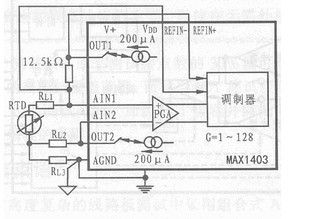
3-wire RTD application circuit The 3-wire RTD utility line consisting of the MAX1403 and a small number of peripheral components is shown in the figure. The two current sources (200μA) in the figure are closely matched to compensate for errors in the 3-wire RTD line. In a 3-wire RTD circuit, if only one current source is applied, the lead resistance will cause an error in the system. At this time, the 200μA current will generate an error voltage through RL1 and be applied to the two upper inputs (AIN1 and AIN2) of the PGA. If you use another current source of the same size and size as the previous current source. Then the current source will also generate an error voltage in RL2, the magnitude of which is the same as the error voltage of RL1, and the direction is opposite, so that the error voltage at the input terminals of AIN1 and AIN2 is zero, that is, it is not affected by the lead resistance. The reference voltage in Figure 3 is provided by the voltage drop of a current source (200μA) at a 12.5kΩ resistor. This setting ensures that the ADC achieves a more accurate ratio result.

Stand Table Fan ,12 Inch Oscillating Table Fan,Pedestal Table Fan,Height Adjustable Table Fan
Foshan Shunde Josintech Electrical Appliance Technology Co.,Ltd , https://www.josintech.com
