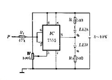
This circuit can be used to detect logic levels whose level change frequency is not too high, and can be detected for both TTL level and CMOS level.
As shown in the figure, the 7555 is used as a hysteresis level comparator. When the probe P is in contact with the high level, the 7555 outputs a low level to make LED1 bright and LED2 dark. When P touches a low level, the 7555 outputs a high level so that LED1 does not illuminate and LED2 illuminates.
When used to measure the TTL level, the power supply can be powered by a 4.5V Battery. The voltage of the 5755 pin of the 7555 is 2.4V. At this time, the 2.4V is high level and the 1.2V level is low level.
When measuring the CMOS level, the power supply voltage needs to be close to the power supply voltage of the logic circuit under test, and the W center head is disconnected. At this time, two-thirds of the power supply voltage is high, and one-third lower than the power supply voltage is low.
In the measurement, the eye will not be able to observe the level of the logic level. This can be estimated according to the different luminous intensity of LED1 and LED2. The pulse duty ratio is greater than 50% or less than 50%. The duty ratio is greater than 50%. Then LED1 is brighter, otherwise LED2 is brighter.
Portable Outdoor Power,Outdoor Power Bank,Outdoor Battery Bank,Outdoor Portable Power
SUZHOU DEVELPOWER ENERGY EQUIPMENT CO.,LTD , https://www.fisoph-power.com
