
Overview:
Multi-output switching power supplies are widely used in various complex electronic systems of low power due to their small size and high cost performance. However, with the development of modern electronic systems, there are increasingly higher requirements for multiple output power sources, such as volume, efficiency, output voltage accuracy, load capacity (output current), cross regulation, ripple and noise. Among them, the cross adjustment rate refers to the rate of change of the output voltage of each power supply when the load current of one of the multiple output power sources changes, which is an important performance indicator for evaluating the multi-output power supply. Influenced by the leakage inductance between the windings of the transformer, the resistance of the winding, the parasitic parameters of the current loop, etc., the cross-regulation rate of the multi-output power supply has always been the design focus of the multi-output switching power supply.
At present, the methods for improving the cross-adjustment rate can be classified into passive and active. The active method requires the addition of additional linear regulation or switching regulator circuits. Although higher cross-regulation rates can be obtained, they are at the expense of power efficiency and cost, and are not as reliable or complex. The passive method is good. When the passive cross-adjustment rate optimization method is mentioned, experienced engineers first think of output voltage-weighted feedback control. Secondly, if the flyback circuit is selected, the cross-adjustment rate can be further optimized by optimizing the coupling of each winding of the transformer and optimizing the clamp circuit. The forward circuit couples the output filter inductors together to further optimize the cross regulation. However, when the above optimization measures have been adopted, or when the design requirements cannot be met, it is usually reluctant to add the dummy load efficiency in exchange for the cross-adjustment rate, or re-elect to the cost-optimized active optimization design.
The following describes a new TDK-Lambda multi-output solution that improves the cross-modulation rate. This solution enables the passive method to further improve the cross-adjustment rate.
As shown in Figure 1, for two output windings with equal turns (Ns1 = Ns2), we bridge a capacitor C1 at the same end of the two transitions, which can improve the cross regulation. 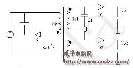
figure 1
For the flyback converter shown in Fig. 1, considering the leakage inductance of each winding, it can be equivalent to the leakage inductance of the windings Ns1, Ns2 and Np of the circuits shown in Fig. 2, Lleak1, Lleak2 and Lleak3, respectively.
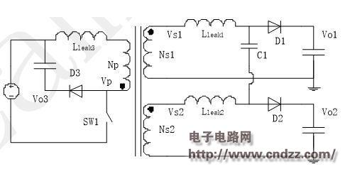
figure 2
Since Ns1=Ns2, there is always Vs1=Vs2 during the whole working process of the power supply, so the circuit can be equivalent to the one shown in Fig. 3, where Is1 and Is2 are the currents flowing through the windings Ns1 and Ns2, respectively.
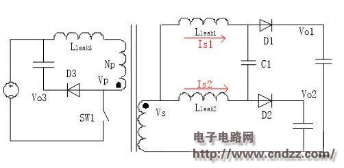
image 3
When the power supply is stable, the average voltage across the inductors Lleak1 and Lleak2 is 0V, so the average DC voltage across the capacitor C1 is also 0V. As the capacitance of capacitor C1 increases, the ripple voltage on the capacitor will become smaller and smaller, so Vo1 will get closer and closer to Vo2, that is, the cross regulation of the power supply will get better and better with the increase of C1 capacity.
(Please read the PDF for details)
Zhejiang Best Nail Industrial Co., Ltd. , https://www.beststaple.com